Handling unicast traffic is easy within the EVPN-VXLAN Data Centre Fabric (DCF) with no worries of handling the BUM, Inter-subnet routing and duplicate traffic. For multicast, that is not always the case. There are challenges in handling multicast in the Centrally Routed Bridge model with a single home or multi-homed environment. Over the time, multiple technologies emerged to overcome these challenges and provide the most efficient way to deliver multicast traffic within and outside of the DCF. This document touches upon the Optimized Inter-Subnet Multicast (OISM) and details the configurations and operational procedures to deploy Express4 based PTX10k in the DCF.
This document assumes that the reader understands EVPN-based Selective Multicast Ethernet Tag (SMET) and Inclusive Multicast Ethernet Tag (IMET) traffic forwarding in a data centre (DC) without optimization. We will test EVPN OISM on Express4 based PTX platforms covering "BD everywhere" model with configuration and operational aspects. "OISM with BD not everywhere" is not covered in this document.
Multicast in EVPN and the problem with the CRB Model
EVPN-VXLAN helps stretching L2 networks across sites at scale and is widely deployed in enterprise data centre networks. Optimized multicast traffic delivery has been supported and deployed in a Centrally Routed Bridge (CRB) Model for a while now.
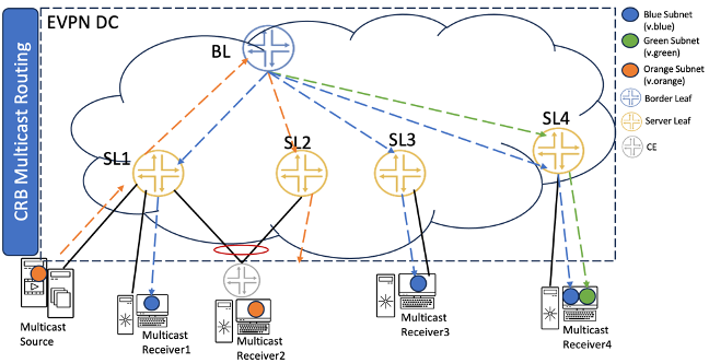
SMET and Assisted Replication (AR) optimizes multicast traffic within a subnet (VLAN) in the CRB model, inter-subnet multicast traffic forwarding still could be handled better in terms of avoiding traffic hair-pinning and reducing core-bandwidth utilization. This is particularly required when there are many subnets with listeners for a multicast flow.
In Figure 1, the traffic from Server Leaf 1 (SL-1) to "Multicast receiver1" goes through the Border Leaf (BL) instead of routing it locally, which consumes the core bandwidth based on the number of flows. This poses a replication load on BL and increases the number of copies of the packet being sent on the core. This is called traffic hair-pinning and it is inefficient: it increases replication on BL and adds latency. If SL1 could route the traffic locally, it would reduce end-to-end latency
For details on the inter-subnet routing forwarding rules refer to the DayOne OISM EVPN book.
Optimized Inter-Subnet Multicast function introduces the following traffic forwarding benefits:
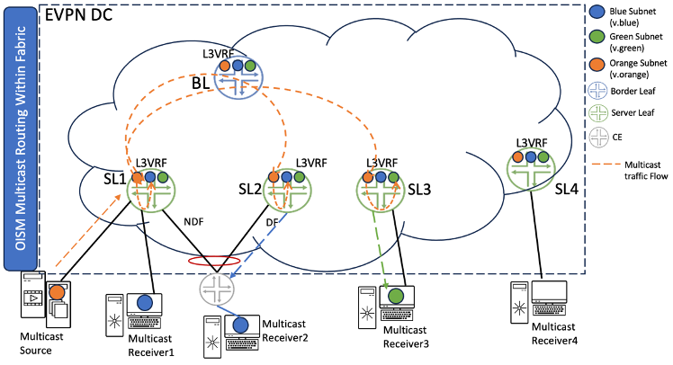
In OISM model the traffic is always switched to the remote receivers using the source VLAN and the downstream multicast receiver gets routed traffic. For example, if multicast traffic is sourced at SL1 (v.orange) and the receiver is on SL3 (v.blue), then the traffic will be EVPN-switched towards SL3 using v.orange only and then routed from v.orange to v.blue locally at SL3.
It reduces latency.
OISM makes the network more reliable as it creates a backup path for traffic in case one Border Leaf fails.
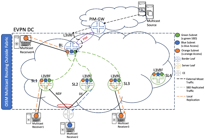
Multicast traffic received from outside fabric is delivered within fabric on Supplementary Bridge Domain (SBD) to receiver's leaves which further route multicast traffic to directly connected receivers.
Table 1 contains the list of supported features for the PTX platforms in 22.3R1 EVO. Please refer to OISM Documentation for the latest and more details updates.OISM Feature Support:
Features
Supported on PTX10000 Chassisand PTX10001-36MR
Intra-VLAN Multicast traffic with IGMP Snooping with Multi-homing consideration for EVPN over VXLAN
YES
Inter-VLAN Multicast traffic and IRB for EVPN over VXLAN
YES
OISM support for EVPN over VXLAN with BDs everywhere for IGMP v2/v3
YES
Role of Server Leaf
YES
Role of Border Leaf with PIM-GW over EVPN-VXLAN IRB/L3 interface/non-EVPN IRB
YES
AE/non-AE/ECMP interface will be supported as underlay/OIF in the multicast route
YES
EVPN Type6 SMET Route to selectively send or receive traffic based on the presence of active receivers
YES
EVPN A/A Multi-homing by using BGP EVPN Type 7/8 NLRIs to sync IGMP joins/leaves received on multi-homed interfaces between multi-homing peer PEs
YES
Distributed DR for EVPN over VXLAN Multicast traffic with OISM
YES
SP and EP style configurations
YES
EVPNoMPLS Snooping
NO
Assisted Replication for both Leaf and Replicator role
In Figure 2 below, "Multicast Source" is behind SL1 on v.orange and the multicast traffic is originated from there. The dotted arrow lines in the figure indicate the multicast traffic flow. The receivers for this multicast traffic are:
Single-homed SL1 on v.blue VLAN [Multicast receiver 1]
Multi-homed SL1/SL2 on v.blue VLAN [Multicast receiver 2]
Single-homed SL3 on v.blue VLAN [Multicast receiver 3]
First SL1 will route the traffic locally from IRB of v.orange VLAN to IRB of v.blue VLAN and send it towards "Multi-homed Receiver 1"
One copy of multicast traffic will be EVPN switched towards SL2 on source VLAN [v.orange] and SL2 will send traffic towards "Multi-homed Receiver 2" as SL2 is the EVPN DF.
One copy of traffic will be EVPN switched towards SL3 on source VLAN [v.orange] and SL3 would route it to IRB of v.green VLAN locally and sent towards "Multicast Receiver 3"
Please note: SL2 and SL3 will not send traffic back to the core post routing traffic from source VLAN to receiver VLAN.
OISM -- Inter-Subnet Multicast from outside fabric (Classic L3)
In the scenario of Figure 3 Border Leaf node is acting as PIM External Gateway (PEG). The dotted arrow lines in the figure represent the multicast traffic flow. Here the multicast source is external to DC fabric and the receivers are:
Single-homed SL1 on v.orange VLAN [Multicast receiver 1]
Multi-homed SL1/SL2 on v.blue VLAN [Multicast receiver 2]
Single-homed SL3 on v.orange VLAN [Multicast receiver 3]
Single-homed BL on v.orange VLAN [Multicast receiver 4]
Traffic flow from the External world to the EVPN DC is described below.
Multicast Traffic pulled from an external source will land on BL (by virtue of pim join sent towards the external source from BL)
Since there is a local receiver "Multicast receiver 4" on BL, it will locally route the traffic to IRB of v.orange VLAN and send it towards "Multicast receiver 4".
BL will also route the traffic to IRB of Supplementary Bridge Domain (SBD) v.green VLAN, since it has received Type6 SMET signalling on SBD VLAN.
Post routing to IRB of SBD VLAN, one copy of multicast traffic will be EVPN switched towards SL1, SL2, and SL3 on v.green VLAN.
On SL1, traffic will be locally routed from IRB of SBD v.green VLAN to IRB of orange VLAN and sent towards "Multicast Receiver 1".
Both SL1 and SL2 will route the traffic from IRB of v.green VLAN to IRB of v.orange VLAN, but only EVPN DF among SL1 or SL2 will send traffic towards "Multicast Receiver 2". In this case, SL2 is the EVPN DF.
On SL3, traffic will be locally routed from IRB of SBD v.green VLAN to IRB of v.orange VLAN and sent towards "Multicast receiver 3".
Please note: SL1, SL2, SL3, and BL will not send traffic back to the core post routing traffic from source VLAN to receiver VLAN. It is not recommended to host any server (unicast/multicast) on SBD to avoid any anomalies like traffic duplication.
We have validated EVPN OISM service on PTX10K platforms powered by Express 4 ASIC and Junos EVO on 400GE interfaces.
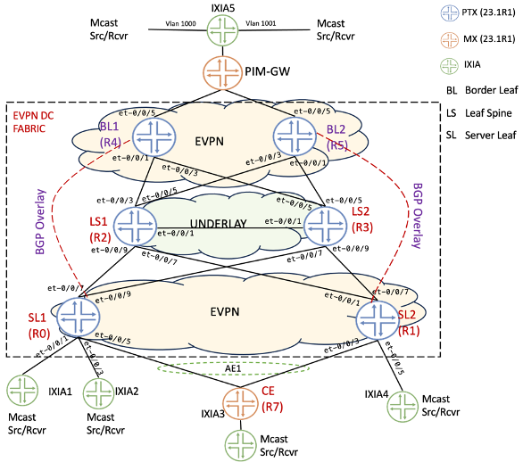
Figure 4 illustrates the reference topology below, used to test OISM with multicast sources and receivers within the data center and outside of the data center domain with PIM-GW as Classic L3 or MVLAN.
PTX platform has been validated in three different roles (see Table 2).
OISM Nodes and Roles:
Node
Details
Border Leaf
PTX10K can be placed as Border Leaf to receive multicast traffic from outside world or to send multicast traffic to outside world from the source within fabric
Leaf Spine
Spine devices are underlay of EVPN Fabric as IP transit devices. The leaf spines might also act as Route Reflectors (RR) in the fabric. PTX10k is capable of playing this role
Server Leaf
PTX10K can be placed as Server Leaf to perform local multicast routing. In this role, the multicast traffic from other SL devices received on source VLAN is routed to receiver VLAN. The multicast traffic from external world (through BL devices) is received on SBD VLAN and is routed to receiver VLAN on the SLs.
For external Multicast we have validated three scenarios (see Table 3).
Mode
Details
External IRB -- MVLAN
The PIM-GW node will be multihomed to the BL nodes with EVPN-VXLAN. So, the PIM-GW will having BGP peering with the BL nodes.
Internal Classic L3 Interface
On the PIM-GW the Multicast source/receivers are connected using a regular L3 interface. The connectivity between PIM-GW and BL is a regular L3 Interface with PIM running.
L3 Over IRB
On the PIM-GW the Multicast source/receivers are connected using L2, terminated on the IRB which is running PIM protocols.
For delivering multicast within the fabric, we have tested scenarios outlined in Table 4.
OISM Terminology:
Bridge Domain / VLAN
Description
Configured on
Multicast VLAN(M-VLAN)
A VLAN in the EVPN fabric with associated IRB interfaces that connect the fabric to an external multicast router. This VLAN and IRB interface enable traffic flow between devices inside and outside the fabric.
Border leaf devices
Extra non-EVPN VLAN
(Non-EVPN IRB method for external multicast). An extra VLAN that isn't in the EVPN instances in the fabric. You configure associated IRB interfaces in the tenant L3 VRF instances. This VLAN and IRB interface enable multicast traffic flow between devices inside the fabric and devices outside the fabric.
Border leaf devices
Revenue Bridge Domains(VLANs)
Bridge domains for subscribers to the services that the fabric provides. You configure the revenue bridge domains as VLANs in the fabric.
All OISM devices
Supplemental Bridge Domain(SBD)
Bridge domain that enables support for external multicast traffic and implements SMET optimization in the EVPN core.
All OISM devices
Table 5 summarises information about router models, roles and Junos releases, helper MX platforms and traffic generators used in the test bed.
Topology devices details:
Device Name
Device Model
Software Release
R0-Server Leaf1
PTX10001-36MR
23.1R1.8-EVO
R1-Server Leaf2
PTX10001-36MR
23.1R1.8-EVO
R2-Spine Leaf1
PTX10001-36MR
23.1R1.8-EVO
R3-Spine Leaf2
PTX10001-36MR
23.1R1.8-EVO
R4-Border Leaf1
PTX10001-36MR
23.1R1.8-EVO
R5-Border Leaf1
PTX10001-36MR
23.1R1.8-EVO
R6-External
MX480
22.4R1.9
R7-CE1
MX480
22.4R1.9
R8, R9, R10, R11 -- Multicast Source/Receivers
Ixia
8.20
Underlay, Overlay and Customer Equipment (CE) Configuration
All the devices including SL, BL, LS and PIM-GW are configured with OSPF as an IGP for underlay layer. For EVPN-VXLAN overlay and exchanging EVPN routes SL are BL nodes are establishing full meshed MS-iBGP sessions for evpn signalling. The Sample configuration of the underlay protocols on PTX and CE configuration of MX router (including SP/EP style configuration) is covered as part of Access/Underlay Configuration & CE configuration - SP/EP Style (check the config snippets at the end of this article).
On BL and SL devices, configure the following knob to originate Type-6 on RevBD where the local IGMP report is received. Without this knob, Type-6 is originated only on SBD alone, as per draft-ietf-bess-evpn-irb-mcast. This knob is provided to enable interop with other vendor devices.
Without this knob, Type-6 is originated on SBD only. This knob enables interoperability with other vendor devices that do not support OISM.
Multicast snooping to install L2 (*,G) forwarding routes in PFE
By default for OISM, the L2(,G) forwarding routes will not be installed in the PFE. To override the default behaviour, use the following knob. This is for scaling considerations for OISM. Hence, use this knob to install L2(,G) routes to PFE
set routing-instance <instance-name> multicast-snooping-options oism install-star-g-routes"
Tunnel-termination is not enabled by default on PTX platforms. User has the option to enable tunnel-termination either globally or at the underlay interface level for VXLAN tunnel termination to work. Use the below command:
"set forwarding-options tunnel-termination"
Enable OISM "BD everywhere" mode on PTX SL and BL nodes by issuing the following knob:
Server Leaves (R0, R1) in Figure 4 have directly connected multicast sources and receivers. CE (R7) is multihomed to SL1 (R0) and SL2 (R1) as active/active ESI LAG with directly connected multicast source/receivers. Border Leaf's (R4, R5) are connected to the PIM-GW (R6) with multicast sources, receivers attached.
Configuration Overview
Each node configuration is detailed towards the end of this document in the Configuration Snippet section with name configured outlined as Access/Underlay, Overlay. Follow below steps to bring up the setup for OISM testing:
Bring up the underlay on the respective SL, BL, PIM-GW using the Access/Underlay section that includes the provisioning of Interfaces (Physical & Loopback), Bundles & IGP. Make sure everything works end-to-end
Once the underlay is all up and reachability is established. Make the overlay configurations
Use the section below to bring up the OISM related configuration on SLs, BLs. Use the given configuration under each sections "SL Configuration" and "PEG Configuration" respectively.
Once we have all the configurations done, simulate the IGMP hosts from IXIA for multicast joins and to send multicast traffic.
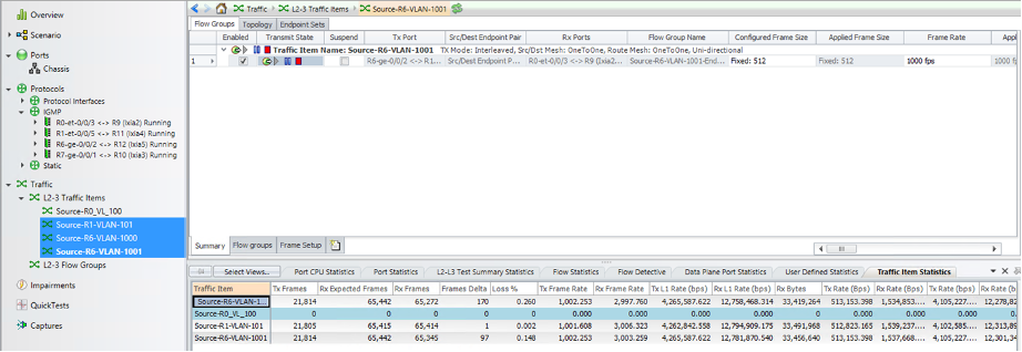
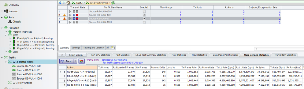
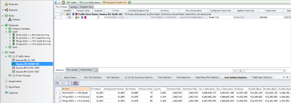
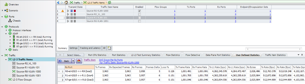
There are multicast sources and receivers connected to PIM-GW, SL1, SL2 and multihomed CE. There are two service VLANs in the DC VLAN100, VLAN101 and one SBD VLAN900 in the topology. There are two multicast group 225.1.1.10, 225.1.1.20 and receivers are associated in VLAN100, VLAN101, VLAN1000, VLAN10001. Below Table 5 lists down the various flows generated for this test.
Multicast Flow
Source
Multicast Group
Receivers (VLAN & Node)
Traffic Rate
SL1-VLAN-101
VLAN101 (101.1.1.3)
225.1.1.10
SL1(100),SL2(100),PIM-GW(1000),MHCE(100)
1000pps
PIM-GW-VLAN-1000
VLAN1000 (25.1.1.2)
225.1.1.10
SL1(100),SL2(100),PIM-GW(1000),MHCE(100)
1000pps
PIM-GW-VLAN-1001
VLAN1001 (25.1.2.2)
225.1.1.10
SL1(100),SL2(100),PIM-GW(1000),MHCE(100)
1000pps
SL1-VLAN-100
VLAN100 (100.1.1.3)
225.1.1.20
SL1(100,101),SL2(100),PIM-GW(1000),MHCE(100,101)
1000pps
Table 1: Multicast Flow details
SL Configuration
Below configuration is focused on the OISM specific configuration on the SLs and the common configurations including underlay/overlay are in the configuration snippets.
The BL Devices in the OISM setup are made EVPN PEG using configuration "protocols evpn oism pim-evpn-gateway" to pull the traffic from the SLs so that BLs can route the traffic to external receivers. SL devices are not required to be configured as PEG.
To configure SBD on all OISM PEs use this configuration "supplemental-bridge-domain-irb irb.". Here It can be configured at the L3 VRF level specifying the IRB associated with the SBD. The same VNI must be configured for the SBD on all the PEs for a particular L3-VRF. The SBD IRB interface should be configured in this L3-VRF instance.
Operational states and corresponding CLI commands Overview
The section below covers different verification CLI commands to check the status of the multicast forwarding on different nodes in the network including the SL, BL, PIM-GW. Table 6 shows the summary of the commands.
Command
Description and Usage
show igmp snooping evpn database
Displays the entries related to bridge domain, vni, multicast group etc.
show igmp snooping evpn membership
Displays the multicast group entries along with the sources, OIFs and report.
show multicast route instance OISM_VRF extensive
This shows the multicast route entries for the active multicast traffic. Shows the downstream and upstream OIFs
show route table bgp.evpn.0 match-prefix 3*
This is check all Type 3 route generated by the router.
show route table bgp.evpn.0 match-prefix 6*
This is check all Type 6 routes generated and learnt by the router.
show route table bgp.evpn.0 match-prefix 7*
Type-7 is for Multicast/IGMP Join Sync
show route table bgp.evpn.0 match-prefix 8*
Type-8 is for Multicast/IGMP Leave
show evpn multicast-snooping next-hops
This is to find out the respective tunnels which is useful for debugging/troubleshooting
show evpn igmp-snooping database extensive l2-domain-id
Print the details on the IGMP snooping database specific to the VLAN, VNI etc.
show evpn igmp-snooping database extensive group
Print the details on Multicast details specific to the Multicast group.
Table 2: CLI commands to verify OISM status on each node
OISM States on SL
The show cli commands below highlights the active receivers for the multicast group based on the sources on VLAN100, VLAN101 and the SBD 900.
The below CLI output shows the Type 3 routes on the SL, which is used for handling the BUM traffic The Ingress replication routes which are critical in building the tunnels are highlighted in the output below. SL1 (R0)
R0-SL1> show route table bgp.evpn.0 match-prefix 6*
bgp.evpn.0: 106 destinations, 106 routes (106 active, 0 holddown, 0 hidden)
+ = Active Route, - = Last Active, * = Both

6:1.1.1.1:1::900::225.1.1.10::1.1.1.1/520
                   *[EVPN/170] 23:23:45
                       Indirect
6:1.1.1.1:1::900::225.1.1.20::1.1.1.1/520
                   *[EVPN/170] 23:23:45
                       Indirect
6:1.1.1.2:1::900::225.1.1.10::1.1.1.2/520
                   *[BGP/170] 23:10:07, localpref 100, from 1.1.1.2
                      AS path: I, validation-state: unverified
                    >  to 10.1.1.1 via et-0/0/7.0
                       to 11.1.1.1 via et-0/0/9.0
6:1.1.1.2:1::900::225.1.1.20::1.1.1.2/520
                   *[BGP/170] 23:09:38, localpref 100, from 1.1.1.2
                      AS path: I, validation-state: unverified
                       to 10.1.1.1 via et-0/0/7.0
                    >  to 11.1.1.1 via et-0/0/9.0
6:1.1.1.5:1::100::0.0.0.0::1.1.1.5/520
                   *[BGP/170] 1d 21:44:08, localpref 100, from 1.1.1.5
                      AS path: I, validation-state: unverified
                       to 10.1.1.1 via et-0/0/7.0
                    >  to 11.1.1.1 via et-0/0/9.0
6:1.1.1.5:1::101::0.0.0.0::1.1.1.5/520
                   *[BGP/170] 1d 21:44:08, localpref 100, from 1.1.1.5
                      AS path: I, validation-state: unverified
                       to 10.1.1.1 via et-0/0/7.0
                    >  to 11.1.1.1 via et-0/0/9.0
6:1.1.1.6:1::100::0.0.0.0::1.1.1.6/520
                   *[BGP/170] 1d 21:46:50, localpref 100, from 1.1.1.6
                      AS path: I, validation-state: unverified
                       to 10.1.1.1 via et-0/0/7.0
                    >  to 11.1.1.1 via et-0/0/9.0
6:1.1.1.6:1::101::0.0.0.0::1.1.1.6/520
                   *[BGP/170] 1d 21:46:50, localpref 100, from 1.1.1.6
                      AS path: I, validation-state: unverified
                       to 10.1.1.1 via et-0/0/7.0
                    >  to 11.1.1.1 via et-0/0/9.0
R1-SL2> show route table bgp.evpn.0 match-prefix 6*
bgp.evpn.0: 106 destinations, 106 routes (106 active, 0 holddown, 0 hidden)
+ = Active Route, - = Last Active, * = Both

6:1.1.1.1:1::900::225.1.1.10::1.1.1.1/520
                   *[BGP/170] 23:27:25, localpref 100, from 1.1.1.1
                      AS path: I, validation-state: unverified
                    >  to 12.1.1.1 via et-0/0/1.0
                       to 13.1.1.1 via et-0/0/7.0
6:1.1.1.1:1::900::225.1.1.20::1.1.1.1/520
                   *[BGP/170] 23:27:25, localpref 100, from 1.1.1.1
                      AS path: I, validation-state: unverified
                       to 12.1.1.1 via et-0/0/1.0
                    >  to 13.1.1.1 via et-0/0/7.0
6:1.1.1.2:1::900::225.1.1.10::1.1.1.2/520
                   *[EVPN/170] 23:13:47
                       Indirect
6:1.1.1.2:1::900::225.1.1.20::1.1.1.2/520
                   *[EVPN/170] 23:13:18
                       Indirect
6:1.1.1.5:1::100::0.0.0.0::1.1.1.5/520
                   *[BGP/170] 23:27:22, localpref 100, from 1.1.1.5
                      AS path: I, validation-state: unverified
                       to 12.1.1.1 via et-0/0/1.0
                    >  to 13.1.1.1 via et-0/0/7.0
6:1.1.1.5:1::101::0.0.0.0::1.1.1.5/520
                   *[BGP/170] 23:27:22, localpref 100, from 1.1.1.5
                      AS path: I, validation-state: unverified
                       to 12.1.1.1 via et-0/0/1.0
                    >  to 13.1.1.1 via et-0/0/7.0
6:1.1.1.6:1::100::0.0.0.0::1.1.1.6/520
                   *[BGP/170] 23:27:20, localpref 100, from 1.1.1.6
                      AS path: I, validation-state: unverified
                       to 12.1.1.1 via et-0/0/1.0
                    >  to 13.1.1.1 via et-0/0/7.0
6:1.1.1.6:1::101::0.0.0.0::1.1.1.6/520
                   *[BGP/170] 23:27:20, localpref 100, from 1.1.1.6
                      AS path: I, validation-state: unverified
                       to 12.1.1.1 via et-0/0/1.0
                    >  to 13.1.1.1 via et-0/0/7.0
The below CLI output show the Type 7 routes on the SLs generated locally or learnt from remote leaves.
R1-SL2> show route table bgp.evpn.0 match-prefix 7*
bgp.evpn.0: 109 destinations, 109 routes (109 active, 0 holddown, 0 hidden)
+ = Active Route, - = Last Active, * = Both

7:1.1.1.1:1::111111111111111111::100::225.1.1.10::1.1.1.1/600
                   *[BGP/170] 00:08:08, localpref 100, from 1.1.1.1
                      AS path: I, validation-state: unverified
                       to 12.1.1.1 via et-0/0/1.0
                    >  to 13.1.1.1 via et-0/0/7.0
7:1.1.1.1:1::111111111111111111::101::225.1.1.20::1.1.1.1/600
                   *[BGP/170] 00:08:07, localpref 100, from 1.1.1.1
                      AS path: I, validation-state: unverified
                    >  to 12.1.1.1 via et-0/0/1.0
                       to 13.1.1.1 via et-0/0/7.0
The below CLI output show the EVPN database and membership details on the SLs. Also it displays the multicast next-hops with its respective VTEP tunnels.
R1-SL2> show evpn igmp-snooping database extensive l2-domain-id 100
Instance: EVPN_OISM
  VN Identifier: 100
        Group IP: 225.1.1.10, Source IP: 0.0.0.0
            Access OIF Count: 1
                  Interface                 ESI             Local    Remote
                ae1.100       00:11:11:11:11:11:11:11:11:11 0           1

R1-SL2> show evpn igmp-snooping database extensive l2-domain-id 101
Instance: EVPN_OISM
  VN Identifier: 101
        Group IP: 225.1.1.20, Source IP: 0.0.0.0
            Access OIF Count: 1
                  Interface                 ESI             Local    Remote
                ae1.101       00:11:11:11:11:11:11:11:11:11 0           1

R1-SL2> show evpn igmp-snooping database extensive group 225.1.1.10
Instance: EVPN_OISM
  VN Identifier: 100
        Group IP: 225.1.1.10, Source IP: 0.0.0.0
            Access OIF Count: 1
                  Interface                 ESI             Local    Remote
                ae1.100       00:11:11:11:11:11:11:11:11:11 0           1
R1-SL2> show evpn igmp-snooping database extensive group 225.1.1.20
Instance: EVPN_OISM
  VN Identifier: 101
        Group IP: 225.1.1.20, Source IP: 0.0.0.0
            Access OIF Count: 1
                  Interface                 ESI             Local    Remote
                ae1.101       00:11:11:11:11:11:11:11:11:11 0           1
R1-SL2> show evpn multicast-snooping next-hops
Family: INET
ID          Refcount KRefcount Downstream interface Addr
47605             21         6 vtep.32770
                               vtep.32771
                               vtep.32772
47475              3         1 vtep.32770
                               vtep.32771
                               vtep.32772
47477              3         1
47479              3         1 vtep.32771
                               vtep.32772
47481              3         1
47483              3         1 vtep.32770
                               vtep.32771
                               vtep.32772
47485              3         1
47487              3         1 vtep.32771
                               vtep.32772
47489              3         1
47467              3         1 vtep.32770
                               vtep.32771
                               vtep.32772
47469              3         1
47471              3         1 vtep.32771
                               vtep.32772
47473              3         1
In EVPN table, the 0.0 mesh group is for CE mesh group and 0.1 mesh group is for VE mesh group. Whereas, the MCSNOOPD table it is other way around 0.0 mesh group is for VE and 0.1 is for CE. The below output taken from the SL1, SL2 shows these routes entries to indicate the routes along with VTEP tunnel association.
The routes in EVPN_OISM.evpn-mcsn.1 are EVPN-MCSN family routes which will be communicated from RPD to MCSNOOPD. These are not used in forwarding and for internal use. These routes and next-hops are used in MCSNOOPD to install routes. The MCSNOOPD routes are ones used for forwarding the multicast traffic.
R0-SL1> show route table EVPN_OISM.evpn-mcsn.1
EVPN_OISM.evpn-mcsn.1: 24 destinations, 24 routes (24 active, 0 holddown, 0 hidden)
+ = Active Route, - = Last Active, * = Both

0.3,0.0,0.0/48     *[Multicast/180] 6d 19:05:14
                       to 1.1.1.5 via vtep.32770
                       to 1.1.1.6 via vtep.32772
                       to 1.1.1.2 via vtep.32771
0.3,0.0,0.0,224.0.0.0/52*[Multicast/180] 6d 19:05:14
                       to 1.1.1.5 via vtep.32770
                       to 1.1.1.6 via vtep.32772
0.3,0.0,0.0,225.1.1.10/80*[Multicast/180] 6d 18:51:36
                       to 1.1.1.5 via vtep.32770
                       to 1.1.1.6 via vtep.32772
                       to 1.1.1.2 via vtep.32771
0.3,0.0,0.0,225.1.1.20/80*[Multicast/180] 6d 18:51:07
                       to 1.1.1.5 via vtep.32770
                       to 1.1.1.6 via vtep.32772
                       to 1.1.1.2 via vtep.32771
0.3,0.1,0.0/48     *[Multicast/180] 6d 19:05:14
0.3,0.1,0.0,224.0.0.0/52*[Multicast/180] 6d 19:05:14
0.3,0.1,0.0,225.1.1.10/80*[Multicast/180] 6d 18:51:36
                       Multicast (IPv4) Composite
0.3,0.1,0.0,225.1.1.20/80*[Multicast/180] 6d 18:51:07
                       Multicast (IPv4) Composite
0.4,0.0,0.0/48     *[Multicast/180] 6d 19:05:14
                       to 1.1.1.5 via vtep.32770
                       to 1.1.1.6 via vtep.32772
                       to 1.1.1.2 via vtep.32771
0.4,0.0,0.0,224.0.0.0/52*[Multicast/180] 6d 19:05:14
                       to 1.1.1.5 via vtep.32770
                       to 1.1.1.6 via vtep.32772
0.4,0.0,0.0,225.1.1.10/80*[Multicast/180] 6d 18:51:36
                       to 1.1.1.5 via vtep.32770
                       to 1.1.1.6 via vtep.32772
                       to 1.1.1.2 via vtep.32771
0.4,0.0,0.0,225.1.1.20/80*[Multicast/180] 6d 18:51:07
                       to 1.1.1.5 via vtep.32770
                       to 1.1.1.6 via vtep.32772
                       to 1.1.1.2 via vtep.32771
0.4,0.1,0.0/48     *[Multicast/180] 6d 19:05:14
0.4,0.1,0.0,224.0.0.0/52*[Multicast/180] 6d 19:05:14
0.4,0.1,0.0,225.1.1.10/80*[Multicast/180] 6d 18:51:36
                       Multicast (IPv4) Composite
0.4,0.1,0.0,225.1.1.20/80*[Multicast/180] 6d 18:51:07
                       Multicast (IPv4) Composite
0.5,0.0,0.0/48     *[Multicast/180] 4d 20:06:54
                       to 1.1.1.5 via vtep.32770
                       to 1.1.1.6 via vtep.32772
                       to 1.1.1.2 via vtep.32771
0.5,0.0,0.0,224.0.0.0/52*[Multicast/180] 4d 20:06:54
                       to 1.1.1.5 via vtep.32770
                       to 1.1.1.6 via vtep.32772
0.5,0.0,0.0,225.1.1.10/80*[Multicast/180] 6d 17:15:14
                       to 1.1.1.5 via vtep.32770
                       to 1.1.1.6 via vtep.32772
                       to 1.1.1.2 via vtep.32771
0.5,0.0,0.0,225.1.1.20/80*[Multicast/180] 6d 17:15:14
                       to 1.1.1.5 via vtep.32770
                       to 1.1.1.6 via vtep.32772
                       to 1.1.1.2 via vtep.32771
0.5,0.1,0.0/48     *[Multicast/180] 4d 20:06:54
0.5,0.1,0.0,224.0.0.0/52*[Multicast/180] 4d 20:06:54
0.5,0.1,0.0,225.1.1.10/80*[Multicast/180] 6d 18:51:36
                       Multicast (IPv4) Composite
0.5,0.1,0.0,225.1.1.20/80*[Multicast/180] 6d 18:51:07
                       Multicast (IPv4) Composite
R1-SL2> show route table EVPN_OISM.evpn-mcsn.1
EVPN_OISM.evpn-mcsn.1: 24 destinations, 24 routes (24 active, 0 holddown, 0 hidden)
+ = Active Route, - = Last Active, * = Both

0.7,0.0,0.0/48     *[Multicast/180] 6d 19:08:03
                       to 1.1.1.1 via vtep.32770
                       to 1.1.1.5 via vtep.32771
                       to 1.1.1.6 via vtep.32772
0.7,0.0,0.0,224.0.0.0/52*[Multicast/180] 6d 19:08:03
                       to 1.1.1.5 via vtep.32771
                       to 1.1.1.6 via vtep.32772
0.7,0.0,0.0,225.1.1.10/80*[Multicast/180] 6d 19:08:03
                       to 1.1.1.1 via vtep.32770
                       to 1.1.1.5 via vtep.32771
                       to 1.1.1.6 via vtep.32772
0.7,0.0,0.0,225.1.1.20/80*[Multicast/180] 6d 19:08:03
                       to 1.1.1.1 via vtep.32770
                       to 1.1.1.5 via vtep.32771
                       to 1.1.1.6 via vtep.32772
0.7,0.1,0.0/48     *[Multicast/180] 6d 19:08:03
0.7,0.1,0.0,224.0.0.0/52*[Multicast/180] 6d 19:08:03
0.7,0.1,0.0,225.1.1.10/80*[Multicast/180] 6d 19:08:08
                       Multicast (IPv4) Composite
0.7,0.1,0.0,225.1.1.20/80*[Multicast/180] 6d 19:08:08
                       Multicast (IPv4) Composite
0.8,0.0,0.0/48     *[Multicast/180] 6d 19:08:03
                       to 1.1.1.1 via vtep.32770
                       to 1.1.1.5 via vtep.32771
                       to 1.1.1.6 via vtep.32772
0.8,0.0,0.0,224.0.0.0/52*[Multicast/180] 6d 19:08:03
                       to 1.1.1.5 via vtep.32771
                       to 1.1.1.6 via vtep.32772
0.8,0.0,0.0,225.1.1.10/80*[Multicast/180] 6d 19:08:03
                       to 1.1.1.1 via vtep.32770
                       to 1.1.1.5 via vtep.32771
                       to 1.1.1.6 via vtep.32772
0.8,0.0,0.0,225.1.1.20/80*[Multicast/180] 6d 19:08:03
                       to 1.1.1.1 via vtep.32770
                       to 1.1.1.5 via vtep.32771
                       to 1.1.1.6 via vtep.32772
0.8,0.1,0.0/48     *[Multicast/180] 6d 19:08:03
0.8,0.1,0.0,224.0.0.0/52*[Multicast/180] 6d 19:08:03
0.8,0.1,0.0,225.1.1.10/80*[Multicast/180] 6d 19:08:08
                       Multicast (IPv4) Composite
0.8,0.1,0.0,225.1.1.20/80*[Multicast/180] 6d 19:08:08
                       Multicast (IPv4) Composite
0.9,0.0,0.0/48     *[Multicast/180] 4d 20:09:48
                       to 1.1.1.1 via vtep.32770
                       to 1.1.1.5 via vtep.32771
                       to 1.1.1.6 via vtep.32772
0.9,0.0,0.0,224.0.0.0/52*[Multicast/180] 4d 20:09:48
                       to 1.1.1.5 via vtep.32771
                       to 1.1.1.6 via vtep.32772
0.9,0.0,0.0,225.1.1.10/80*[Multicast/180] 6d 17:18:08
                       to 1.1.1.1 via vtep.32770
                       to 1.1.1.5 via vtep.32771
                       to 1.1.1.6 via vtep.32772
0.9,0.0,0.0,225.1.1.20/80*[Multicast/180] 6d 17:18:08
                       to 1.1.1.1 via vtep.32770
                       to 1.1.1.5 via vtep.32771
                       to 1.1.1.6 via vtep.32772
0.9,0.1,0.0/48     *[Multicast/180] 4d 20:09:48
0.9,0.1,0.0,224.0.0.0/52*[Multicast/180] 4d 20:09:48
0.9,0.1,0.0,225.1.1.10/80*[Multicast/180] 6d 19:08:08
                       Multicast (IPv4) Composite
0.9,0.1,0.0,225.1.1.20/80*[Multicast/180] 6d 19:08:08
                       Multicast (IPv4) Composite
The below CLI output shows the routes for mesh-groups all_ces_ and __ves__created to manage the multicast traffic replication and duplicates that could possibly be created by the leaf nodes. Also the below highlighted are the next hops programmed for the corresponding routes and the vteps tunnels that are created between the SLs and BLs.
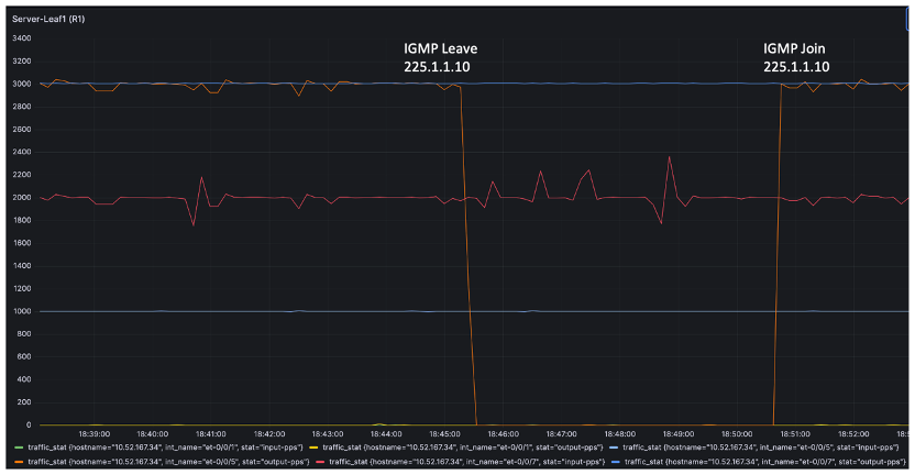
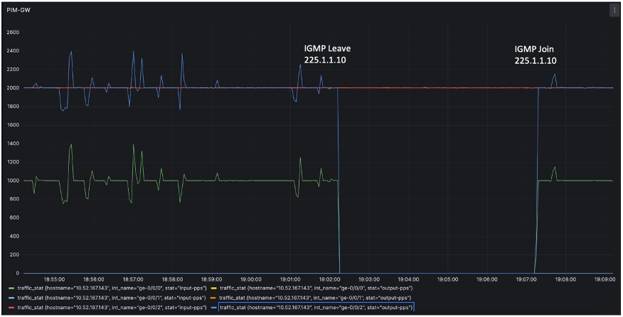
Below tests focus on testing the Multicast group leave and joins to demonstrate that the OISM is responsive to the Leave and Join events not just in the local DC domain but also to the traffic all the way to the Multicast source & receivers connected with the PIM-GW. The CLI commands below shows the states of SL1 and SL2 when IXIA simulates Multicast group Leave and Joins respectively.
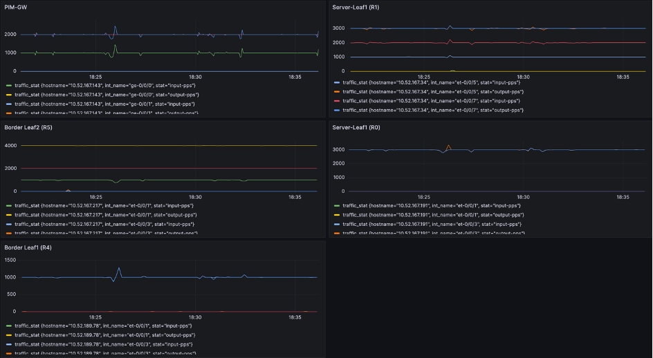
Figure 10 below shows the multicast traffic drop and rampup during IGMP leave and Join events on SL1 of the OISM topology. These statistics shown below in Figure 10 or 11 are polled from the routers corresponding interfaces. The IGMP hosts connected from SL1 to Ixia simulate Leave and Join events.
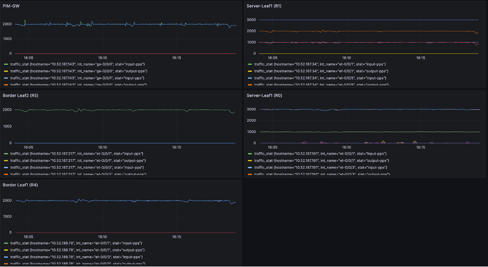
Figure 11 below shows the multicast traffic drop and rampup during IGMP leave and Join events on PIM-GW of the OISM topology. The IGMP hosts connected from PIM-GW directly to Ixia on vlan 1000 simulate Leave and Join events. This is particularly on multicast group 225.1.1.10.
In OISM External IRB MVLAN model there is no changes in SL configurations. However, BL and PIM-GW undergoes major additions and modifications that include LAG and MVLAN instance related configurations. Below section will focus on the configuration additions on BL and PIM-GW only and the complete underlay, overlay and access side configuration are covered in the Configuration Snippet section.
Below section covers the different verification CLI commands to check the status of the multicast forwarding on different nodes in the network including the SL, BL, PIM-GW.
There are two different scenarios of traffic flow:
Multicast source resides in the EVPN DC and the traffic flows out to PIM GW externally.
Traffic comes into the EVPN DC from the multicast source connected externally on PIM GW.
The show cli commands below highlights the states of Multicast on the BL and PIM GW, where the active source resides within the EVPN DC and the receivers are within the DC and also in externally connected.
R6-PIM-GW> show pim join extensive
Instance: PIM.master Family: INET
R = Rendezvous Point Tree, S = Sparse, W = Wildcard

Group: 225.1.1.10
    Source: *
    RP: 1.1.1.7
    Flags: sparse,rptree,wildcard
    Upstream interface: Local
    Upstream neighbor: Local
    Upstream state: Local RP
    Uptime: 1w4d 08:42:07
    Downstream neighbors:
        Interface: irb.2000 (assert winner)
            80.1.1.50 State: Join Flags: SRW Timeout: 176
            Uptime: 02:12:34 Time since last Join: 00:00:34
            80.1.1.60 State: Join Flags: SRW Timeout: 176
            Uptime: 02:11:34 Time since last Join: 00:00:34
            Assert Winner: 80.1.1.70 Metric: 0 Pref: 2147483648 Timeout: 55
        Interface: ge-0/0/2.1001
            25.1.2.1 State: Join Flags: SRW  Timeout: Infinity
            Uptime: 04:32:06 Time since last Join: 02:12:46
    Number of downstream interfaces: 2
    Number of downstream neighbors: 3

Group: 225.1.1.10
    Source: 101.1.1.3
    Flags: sparse,spt
    Upstream interface: irb.2000
    Upstream neighbor: 80.1.1.50
    Upstream state: Local RP, Join to Source, No Prune to RP
    Keepalive timeout: 311
    Uptime: 02:12:34
    Downstream neighbors:
        Interface: irb.2000 (pruned)
            80.1.1.50 State: Prune Flags: SR Timeout: 176
            Uptime: 02:12:34 Time since last Prune: 00:00:34
            80.1.1.60 State: Prune Flags: SR Timeout: 176
            Uptime: 02:11:34 Time since last Prune: 00:00:34
        Interface: ge-0/0/2.1001
            25.1.2.1 State: Join Flags: S   Timeout: Infinity
            Uptime: 02:12:25 Time since last Join: 02:12:25
    Number of downstream interfaces: 2
    Number of downstream neighbors: 3

<SNIP>
R6-PIM-GW> show multicast route extensive
Instance: master Family: INET

Group: 225.1.1.10
    Source: 101.1.1.3/32
    Upstream interface: irb.2000
    Downstream interface list:
        ge-0/0/2.1001
    Number of outgoing interfaces: 1
    Session description: Unknown
    Statistics: 491 kBps, 1002 pps, 9148322 packets
    Next-hop ID: 1048575
    Upstream protocol: PIM
    Route state: Active
    Forwarding state: Forwarding
    Cache lifetime/timeout: 360 seconds
    Wrong incoming interface notifications: 0
    Uptime: 02:32:10

Instance: master Family: INET6

R6-PIM-GW> monitor interface traffic
R6-re0                            Seconds: 16                  Time: 09:28:49

Interface    Link  Input packets        (pps)     Output packets        (pps)
 ge-0/0/0      Up     1116101154       (1005)          2403761          (1)          >>>>>>>> Interface connected to BL1 (R4)
 lc-0/0/0      Up              0                             0
 pfh-0/0/0     Up              0                             0
 ge-0/0/1      Up         303472          (0)       1209892130          (0)
 ge-0/0/2      Up     1228012918          (0)       1735868562       (1005)          >>>>>>>> Interface connected to IXIA
Case 2. External multicast source.
The show cli commands below highlights the states of multicast routes on the BL and PIM GW, where the active source resides within the EVPN DC and some receivers are within the DC and others are connected externally.
R5-BL2> show pim join instance OISM_VRF extensive

Instance: PIM.OISM_VRF Family: INET
R = Rendezvous Point Tree, S = Sparse, W = Wildcard

Group: 225.1.1.10
    Source: *
    RP: 1.1.1.7
    Flags: sparse,rptree,wildcard
    Upstream interface: irb.2000
    Upstream neighbor: 80.1.1.70
    Upstream state: Join to RP
    Uptime: 04:52:06
    Downstream neighbors:
        Interface: irb.900
            90.1.1.60 State: Join Flags: SRW  Timeout: Infinity
            Uptime: 04:52:06 Time since last Join: 02:53:17
        Interface: irb.2000
            80.1.1.50 State: Join Flags: SRW Timeout: 198
            Uptime: 02:52:12 Time since last Join: 00:00:12
    Number of downstream interfaces: 2
    Number of downstream neighbors: 2

Group: 225.1.1.10
    Source: 25.1.1.2
    Flags: sparse,spt
    Upstream interface: irb.2000
    Upstream neighbor: 80.1.1.70
    Upstream state: Join to Source, No Prune to RP
    Keepalive timeout: 107
    Uptime: 00:04:13
    Downstream neighbors:
        Interface: irb.900
            90.1.1.60 State: Join Flags: S   Timeout: Infinity
            Uptime: 00:04:13 Time since last Join: 00:04:13
        Interface: irb.2000
            80.1.1.50 State: Join Flags: S Timeout: 198
            Uptime: 00:04:13 Time since last Join: 00:00:12
    Number of downstream interfaces: 2
    Number of downstream neighbors: 2
Group: 225.1.1.10
    Source: 101.1.1.3
    Flags: sparse,spt
    Upstream interface: irb.101
    Upstream neighbor: Direct
    Upstream state: Local Source, Prune to RP
    Keepalive timeout: 0
    Uptime: 04:52:03
    Downstream neighbors:
        Interface: irb.900
            90.1.1.60 State: Join Flags: S   Timeout: Infinity
            Uptime: 04:52:03 Time since last Join: 04:52:03
        Interface: irb.2000
            80.1.1.50 State: Prune Flags: SR Timeout: 198
            Uptime: 02:52:12 Time since last Prune: 00:00:12
            80.1.1.70 State: Join Flags: S Timeout: 207
            Uptime: 02:52:02 Time since last Join: 00:00:02
    Number of downstream interfaces: 2
    Number of downstream neighbors: 3

<SNIP>
R5-BL2> monitor interface traffic

R5-re0-re0                        Seconds: 747                 Time: 09:46:12

Interface    Link  Input packets        (pps)     Output packets        (pps)

 ae0           Up     1209975390          (1)           398595          (1)
 dsc           Up              0          (0)                0          (0)
 esi           Up              0          (0)                0          (0)
 et-0/0/1      Up      989735767          (1)       2420640210       (2005)
 et-0/0/3      Up      174142714          (0)           630008          (0)
 et-0/0/5      Up     1209975390          (1)           398595          (1)
 et-0/0/7      Up        3173525       (1003)       1210993710       (1003)
 et-0/0/9      Up              0          (0)            66133          (0)
 et-0/0/11     Up              0          (0)            66134          (0)
 et-0/0/13     Up              0          (0)            66138          (0)
 et-0/0/15     Up              0          (0)            66149          (0)
This article has been co-written by Abdul Nasir M and Ramdas Machat.
Thanks to Abdul Nasir, Vikram Nagarajan, Muniyappan Suruttaiyan, Nicolas Fevrier, Vasily Mukhin for their feedback and review comments on this document. Thanks to Kowsalya B S for preparing the vLAB topologies.