Juniper adds support for inline IPsec on MX-series routers, meaning that IPsec encryption/decryption is done directly by the router's Packet Forwarding Engine (PFE) ASIC instead of by a separate service card, resulting in much higher VPN throughput and lower latency.
This Techpost details how inline IPsec works on Trio 6-based MX routers and describes the configuration steps needed to activate it.
Co-written by Poorna Pushkala Balasubramanian and Suneesh Babu
Internet Protocol security (IPsec) is a protocol suite for securing Internet Protocol (IP) communications by authenticating and encrypting each IP packet of a communication session. IPsec also includes protocols for establishing mutual authentication between agents at the beginning of the session and negotiation of cryptographic keys to be used during the session. Juniper's IPSec implementation supports securing both IPv4 and IPv6 network layers by providing data confidentiality, integrity, origin authentication, replay protection, and non-repudiation of source. The Junos OS combines IPSec with Internet Key Exchange (IKE), which automates the secure generation and management of cryptographic keys and Security Associations (SAs) necessary for establishing encrypted tunnels.
Juniper Inline IPsec is a state-of-the-art feature integrated into Junos OS that offloads IPsec encryption and decryption operations from the CPU to the Packet Forwarding Engine (PFE) ASIC on Juniper routers like the MX304, MX301 or MX10000 Line Cards (based on Trio 6 PFE).
This architectural design enables the MX series routers to deliver hardware-accelerated, high-throughput IPsec VPN capabilities without relying on traditional service cards (such as MS-MPC or SPC3), significantly enhancing performance and reducing latency.
A Security Association (SA) is a one-way (inbound or outbound) agreement between two communicating peers, that specifies the IPsec protections to be provided to their communications. A typical bidirectional IPSec connection will have two Security Associations, one in each direction. Each SA specifies a Security Parameters Index (SPI), a destination address and the IPSec Encapsulation Protocol. Juniper supports both manual and dynamic SAs. Manual SAs require static configuration of keys and security parameters on both ends. In contrast, dynamic SAs are negotiated using IKE protocols, both IKEv1 and the more modern, flexible IKEv2 are supported. IKE handles mutual authentication, key agreement, and the creation of secure bidirectional communications. Inline IPSec of MX304 supports only IKEv2.
Juniper IPSec supports strong cryptographic algorithms including AES (Advanced Encryption Standard) for encryption with granular key sizes (128-bit and 256-bit), and SHA-256 for authentication, providing compliance with high security standards such as FIPS and Common Criteria. The Encapsulating Security Payload (ESP) protocol is used to ensure confidentiality and integrity of the tunneled data while also offering anti-replay protection by default.
The Unified Services Framework (USF) enables next generation services on MX. This also enables inline IPSec, without relying on external service cards or modules. Enabling USF mode requires a system reboot. Enabling this mode starts various services-related daemons on JUNOS. The CLI configuration for inline services differs between USF mode and non-USF mode, so the router must be in base configuration before enabling this mode and a reboot is required.
regress@rtme-mx304-09> show system unified-services status
Unified Services : Disabled

regress@rtme-mx304-09> request system enable unified-services
Before enabling unified services, please move to baseline configuration.
Are above conditions satisfied ? [yes,no] (no) yes

Verified junos-unified-services signed by PackageDevelopmentECP256_2025 method ECDSA256+SHA256
NOTICE: 'pending' set will be activated at next reboot...
Unified-Services upgrade staged. Please reboot with 'request system reboot' command to complete the upgrade

regress@rtme-mx304-09> request system reboot
Reboot the system ? [yes,no] (no) yes


*** FINAL System shutdown message from regress@rtme-mx304-09 ***

System going down IMMEDIATELY


Shutdown NOW!
[pid 69698]
Note: Make sure that we are triggering the command on both the RE's explicitly
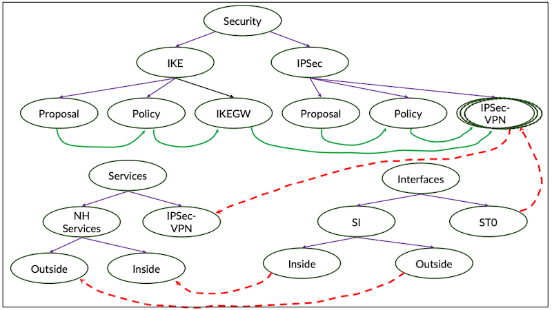
A Service Interface (SI) is a virtual physical interface that resides on the Packet Forwarding Engine (PFE) or lookup engine of the ASIC. The SI interface is also called Anchor interface, which enables advanced services like PPPoE, L2TP, MLPPP and IPSec VPN Processing. The SI interface on MX is the anchor for inline cryptographic processing, eliminating the need for separate service cards or PICs.
Configuring the inline-services creates the "si" interfaces. Four "si" interfaces will be created per Trio 6 ASIC, ie. two per PFE.
regress@rtme-mx304-09> show configuration groups IPSec_T1 chassis
fpc 0 {
    pic 1 {
        inline-services;
    }
}

regress@rtme-mx304-09> show interfaces terse |match si-
si-0/1/0                up    up
si-0/1/1                up    up
si-0/1/2                up    up
si-0/1/3                up    up
We can also specify the bandwidth for the inline-services
[edit groups IPSec_T1 chassis fpc 0 pic 1]
regress@PE1# set inline-services bandwidth ?
Possible completions:
  <bandwidth>          Bandwidth reserved for tunnel service
  100g                 100 gigabits per second
  10g                  10 gigabits per second
  1g                   1 gigabit per second
  200g                 200 gigabits per second
  20g                  20 gigabits per second
  300g                 300 gigabits per second
  30g                  30 gigabits per second
  400g                 400 gigabits per second
  40g                  40 gigabits per second
  50g                  50 gigabits per second
  60g                  60 gigabits per second
  70g                  70 gigabits per second
  800g                 800 gigabits per second
  80g                  80 gigabits per second
  90g                  90 gigabits per second
Here "si-0/1/0" and "si-0/1/1" for the first PFE and "si-0/1/2" and "si-0/1/3" for the second PFE.
Secure Tunnel Interface (ST0) is an internal interface used for route-based IPSec VPNs. It is a virtual interface that routes the cleartext traffic towards an IPSec VPN Tunnel. Each logical unit of st0, like st0.1, st0.2, st0.3 etc corresponds to a separate VPN instance.
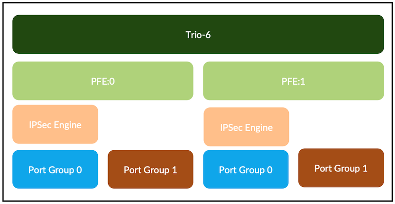
Trio 6 chip has an IPSec engine in the ASIC, which is part of the packet processing chip and does IPsec inline.
Each Trio 6 has two slices, so two engines. Each slice is a PFE, as it is a fabric destination. Each PFE has one IPSec engine. One IPSec engine can handle 300Gbps half-duplex IPsec traffic. Each IPSec Engine provides 1,000 tunnels, so Trio 6 support a total of 2,000 IPSec Tunnels.
Figure 1: High level view of the Trio 6 PFE
Inline IPSec on Trio 6 based MX platforms (MX304, MX301, LC9600, LC4800, LC4802) works with USF in two modes:
Traffic Selector mode coming in Junos 25.4 release
P2P next-hop mode supported since 24.2R1
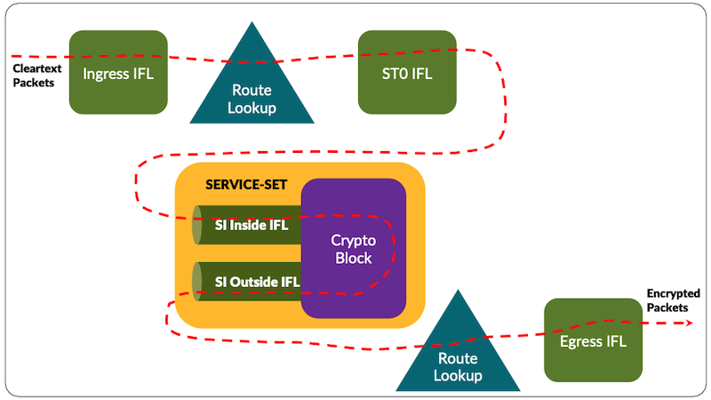
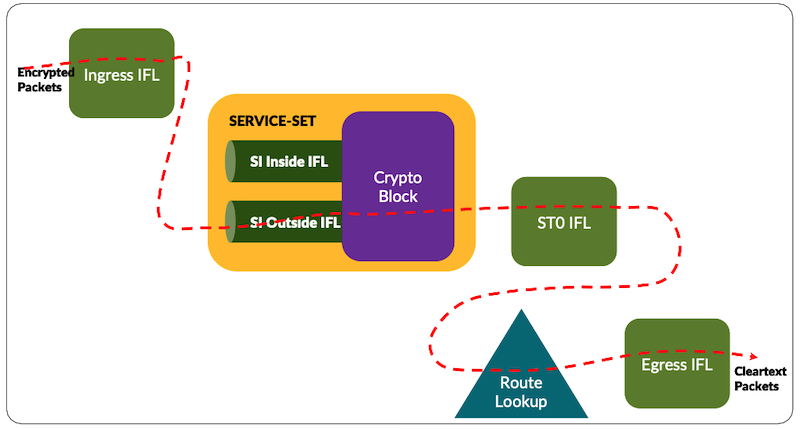
In P2P mode, routing protocol sees unique st0 logical interface for each tunnel (we will present them as "ifl" in the rest of this document). Protocols add routes with next-hop as st0 ifl. There is one to one mapping with st0 ifl and the tunnel Id. The packet is steered towards the st0 ifl based on route look up in the forwarding path. In this case, each si ifl can be mapped to multiple st0 ifl. In P2P case, the number of tunnels supported is limited by the number of st0 ifl that can be configured in the chassis.
Traffic selection mode configuration is described in the scale tests section of this document.
In USF P2P mode, there is a static route that points to a st0.x ifl. There is one st0 ifl per tunnel. The packet is steered towards the st0 ifl based on route look up in the forwarding path for encryption. After the route lookup, WAN packets are forwarded to the st0.x interface. They are then passed to the* "si-inside IFL", which feeds them into the crypto block. Once encrypted, the packets exit through the* "**si-outside IFL" and continue toward the forwarding next hop.
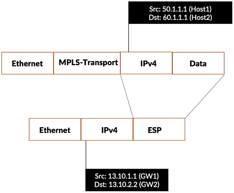
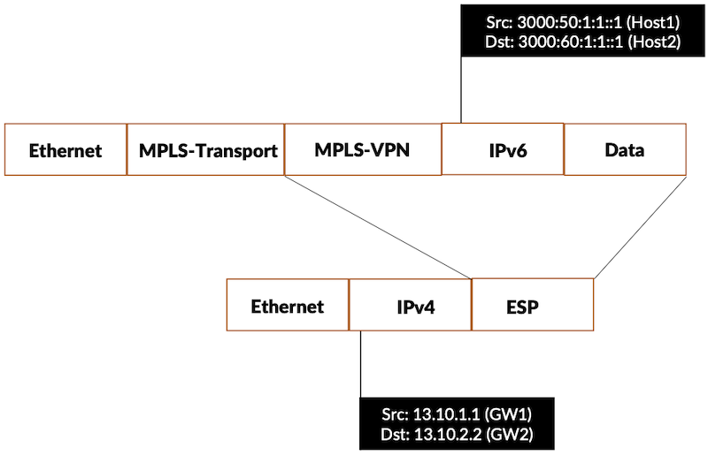
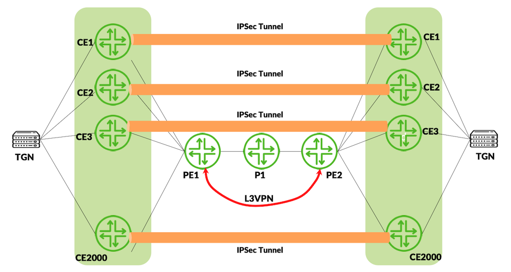
In the test topology PE routers are having BGP peering for IPv4 and IPv6 family with service provider core running with ISIS SR-MPLS. The CE's are simulated on the traffic generator, PE's and CE's are having EBGP peering for both IPv4 and IPv6 family and CE's advertise 100 routes for each IP family. Traffic is set for both families in bi-directional mode.
regress@PE1> show route 3000:60:1:1::1

inet6.0: 209 destinations, 209 routes (209 active, 0 holddown, 0 hidden)
+ = Active Route, - = Last Active, * = Both

3000:60:1:1::/64   *[BGP/170] 3d 16:31:06, localpref 100, from 12.1.1.2
                      AS path: 20002 I, validation-state: unverified
                    >  via st0.1, Push 17
The detailed output shows the PNH as the IPv4 mapped IPv6 address, which got pointed to the secure tunnel interface
EVPN-VXLAN is a modern data center and campus fabric technology that combines Ethernet VPN as the control plane with VXLAN as the overlay data plane to provide scalable Layer 2 and Layer 3 connectivity over an IP underlay network. In this model, VXLAN encapsulates Ethernet frames into UDP packets using a 24-bit VXLAN Network Identifier (VNI), allowing millions of isolated virtual networks that can span across racks, pods, or even multiple sites without relying on traditional spanning tree. EVPN uses MP-BGP to advertise MAC and IP reachability between VXLAN Tunnel Endpoints (VTEPs), enabling control-plane based MAC learning, reduced flooding, and features such as all-active multihoming and distributed anycast gateways for optimized east-west traffic. Together, EVPN and VXLAN deliver a highly scalable, multi-tenant, and resilient overlay fabric that is now a de facto standard for cloud data centers and large enterprise networks.
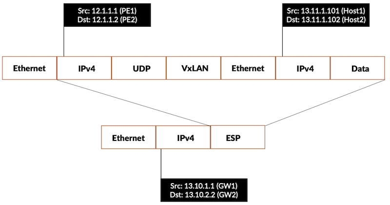
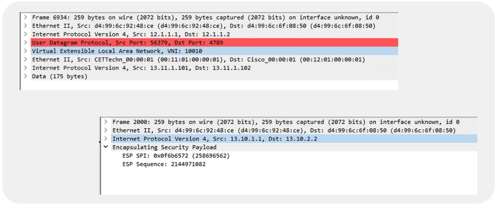
The VXLAN traffic can be secured with IPSec. In the below topology, EVPN-VXLAN is brought between the PE's and VXLAN traffic is tunneled via the IPSec.
regress@PE1> show mac-vrf routing database
Instance: evpn_vxlan_1
VLAN  DomainId  MAC address        Active source                  Timestamp        IP address
     10010      00:00:5e:00:01:01  05:00:00:fc:00:00:00:27:1a:00  Nov 27 20:54:39  13.11.1.254
     10010      00:11:01:00:00:01  et-0/2/10.10                   Nov 27 20:52:40
     10010      00:12:01:00:00:01  12.1.1.2                       Nov 27 20:54:39
     10010      a4:7f:1b:ce:2a:91  12.1.1.2                       Nov 27 20:54:39  13.11.1.2
     10010      d4:99:6c:92:48:fc  irb.10                         Nov 27 20:52:40  13.11.1.1
     10020      00:00:5e:00:01:01  05:00:00:fc:00:00:00:27:24:00  Nov 27 20:54:39  13.11.2.254
     10020      a4:7f:1b:ce:2a:91  12.1.1.2                       Nov 27 20:54:39  13.11.2.2
     10020      d4:99:6c:92:48:fc  irb.20                         Nov 27 20:52:40  13.11.2.1

regress@PE1> show mac-vrf forwarding mac-ip-table

MAC IP flags  (S - Static, D - Dynamic, L - Local , R - Remote, Lp - Local Proxy,
               Rp - Remote Proxy,  K - Kernel, RT - Dest Route, (N)AD - (Not) Advt to remote,
               RE - Re-ARP/ND, RO - Router, OV - Override, Ur - Unresolved, B - Blocked,
               RTS - Dest Route Skipped, RGw - Remote Gateway, RTF - Dest Route Forced,
               SC - Static Config, P - Probe, NLC - No Local Config, LD - Local Down)
 Routing instance : evpn_vxlan_1
 Bridging domain : V_10
   IP                           MAC                  Flags              GBP    Logical            Active
   address                      address                                 Tag    Interface          source
   13.11.1.254                  00:00:5e:00:01:01    S,K                       irb.10
   13.11.1.2                    a4:7f:1b:ce:2a:91    SR,K,RT                   vtep.32769         12.1.1.2
   13.11.1.1                    d4:99:6c:92:48:fc    S,K                       irb.10

MAC IP flags  (S - Static, D - Dynamic, L - Local , R - Remote, Lp - Local Proxy,
               Rp - Remote Proxy,  K - Kernel, RT - Dest Route, (N)AD - (Not) Advt to remote,
               RE - Re-ARP/ND, RO - Router, OV - Override, Ur - Unresolved, B - Blocked,
               RTS - Dest Route Skipped, RGw - Remote Gateway, RTF - Dest Route Forced,
               SC - Static Config, P - Probe, NLC - No Local Config, LD - Local Down)
 Routing instance : evpn_vxlan_1
 Bridging domain : V_20
   IP                           MAC                  Flags              GBP    Logical            Active
   address                      address                                 Tag    Interface          source
   13.11.2.254                  00:00:5e:00:01:01    S,K                       irb.20
   13.11.2.2                    a4:7f:1b:ce:2a:91    SR,K,RT                   vtep.32769         12.1.1.2
   13.11.2.1                    d4:99:6c:92:48:fc    S,K                       irb.20
The IPSec stats captures the packets encrypted and decrypted
Trio 6 based MX platforms support 2,000 Inline IPSec Tunnels per chassis. Each PFE supports 1,000 tunnels. The throughput supported is 600Gbps per Trio 6 ASIC. The scale of the tunnels is covered with inline IPSec's traffic selection mode. In the traffic selector mode, we explicitly map the source and destination addresses in the IPSec VPN and there is no requirement to map the route to st0 via static route. IKED adds a route based on the remote-ip, instead of user adding a static route or BGP/IGP adding routes. Traffic Selector mode provides more granularity to steer the traffic of specific interest to a IPVPN tunnel.
In the test topology 2,000 virtual routers are created in the CE which forms the ebgp peering with the PE devices. Inline IPSec tunnel is setup between the respective CE's with traffic selector mode, 1,000 tunnels created from PFE0 (si-2/1/0) and 1,000 tunnels created from PFE1(si-2/1/2)
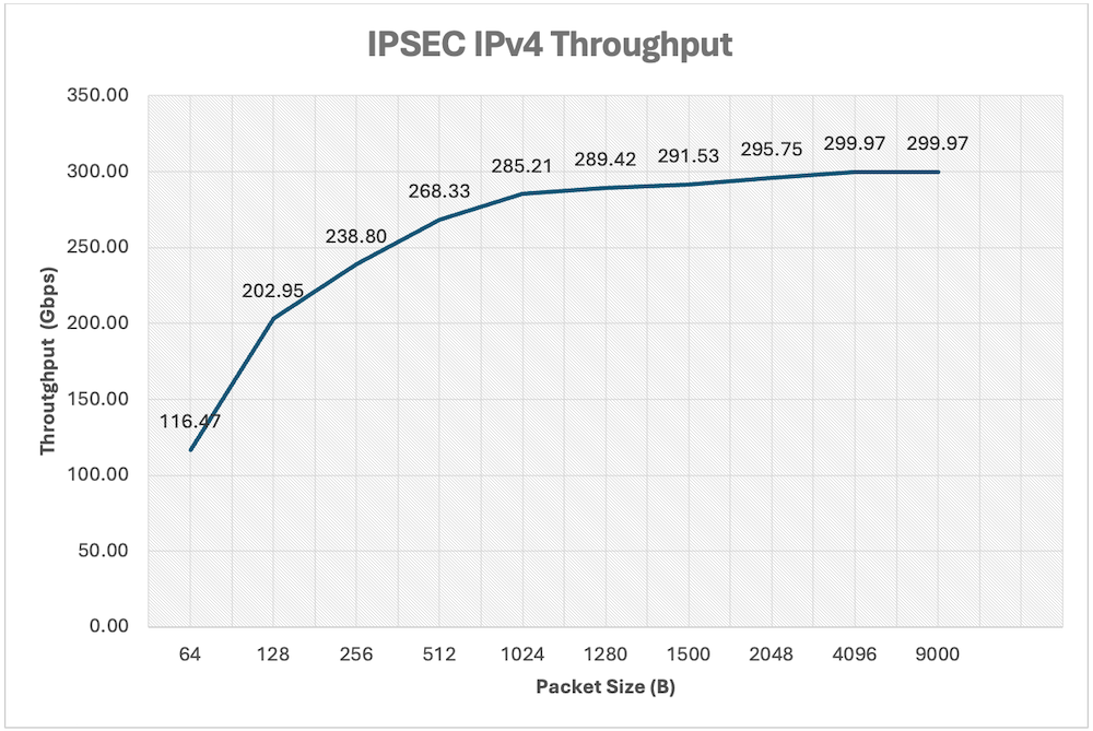
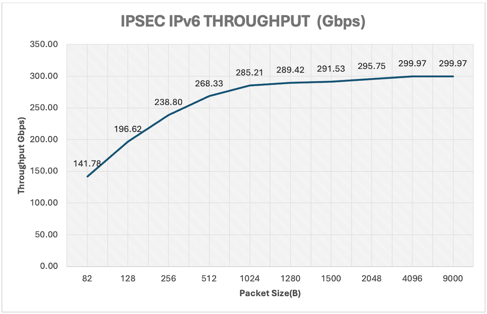
MX304 inline IPSec provides 300Gbps bandwidth per PFE and IPv4 and IPv6 performance on a single PFE is captured as follows. Total thoughput per Trio 6 is 600Gbps
CPU: Central Processing Unit, the general-purpose processor of the router (implied, contrasted with PFE)
DPD: Dead Peer Detection, a mechanism to verify the liveliness of the IKE peer to prevent black-holing of IPsec traffic.
ESP: Encapsulating Security Payload, the IPsec protocol used for encrypting and ensuring the integrity of tunneled data.
IKE: Internet Key Exchange, the protocol used to negotiate cryptographic keys and establish Security Associations (SAs) for IPsec.
IKEv2: Version 2 of IKE, the modern version of the key-management protocol supported by inline IPsec on MX platforms.
SA: Security Association, a one-way agreement between two endpoints that defines the IPsec protections (encryption, integrity, keys, lifetime) for traffic.
SI: Service Interface, a virtual interface on the PFE used as the anchor for inline services (like IPsec) without requiring external service cards.
SPI: Security Parameter Index, a unique identifier for an SA on a host or router.
USF: Unified Services Framework, a configuration mode on MX routers that must be enabled to support inline IPsec (instead of relying on external service cards).
I would like to thank my co-author Poorna Pushkala Balasubramanian for sharing the insights of the implementation and countless hours of support. I also extend my thanks to Sanjeev Venkatrao and Vidya Sagar Chitturi, who performed the scale and performance tests and also to the reviewers Arnav Shrivastava , VimalKumar Patel, David Roy, Nikhil Rao, Sandeep Patel and Nicolas Fevrier.