It's not every day you unveil a brand-new series product line, so it's with a lot of excitement we launched the PTX12000 modular chassis in February 2026.
The PTX12000 chassis sets new standards in terms of port density (800GbE today, 1.6TE will come next), cooling capacity and power efficiency. The new chassis completes the PTX10000 family by adding a different form factor and a fully redesigned architecture. Both the latest line cards and fabric cards for PTX10000 and PTX12000 use the same internal packet-forwarding engine: the Express 5 ASICs.
The new system will be released in two form factors:
An 8-slot chassis that measures 22RU and is already shipping
A 12-slot version, 32RU, planned for the end of the calendar year 2026 (contact your favorite HPE representative for the latest details).
And day 1, they can be populated with two types of line cards:
54 ports 800GbE OSFP
54 ports 800GbE QSFP-DD
This article will provide an extensive description of the hardware (line cards, fabric cards, routing boards, fan trays and power modules), but we will cover also the interfaces and the port capabilities.
Many other publications will follow and will be linked from this page when they appear online.
As a prerequisite, for more details on the Packet Forwarding Engine and the Express5 variants, we invite you to read the following blog posts first:
In this section, we'll illustrate the description with details on the 8-slot chassis, but all these concepts apply to the 12-slot version too, unless otherwise specified.
Figure 02 above provides a front view of the chassis in diverse situations:
Left: with the EMI protective door installed
Center: with line cards and routing engine inserted
Right: without any FRU (Field Replaceable Unit) installed, except the fan trays and one fabric card.
Let's describe the chassis starting from the top.
In front of the power shelf (we will cover it later), you'll find a "Front Panel Display". It's a touch screen an on-site operator can use to visualize the various alarms and verify the chassis parts and interfaces states.
Below the display, two slots are available for the Routing and Control Boards (RCB), also called "Routing Engines" (RE). The system can be operated with one or two REs present. They handle the control and management planes functions, but they also control and monitor the entire chassis internals. If you operate the system with two REs, they become fully redundant (active/standby).
Below the REs, we have 8 or 12 horizontal slots for 2.75 inches line cards. At the date of this article creation, two flavors of line cards are available, both offering 54 ports 800GbE with different optics form-factors. It represents 43.2Tbps of port connectivity but also 43.2Tbps of forwarding capability (the cards are not oversubscribed). More line cards will be introduced in the future, and the system is designed to support 1.6T optics.
The following chart describes the maximum port density per interface type/speed at launch day:
Pluggable Optics Modules
Maximum Port Densityper Slot
Maximum Port Densityper PTX12008
Maximum Port Densityper PTX12012
800Gbps
54
432
648
400Gbps
108 (w/ 2x400G)
864
1,296
100Gbps
432 (w/ 8x100G)
3,456
5,184
40Gbps
54 (QSFP only)
432
648
25Gbps
216 (w/ 4x25G, QSFP only)
1,728
2,592
10Gbps
216 (w/ 4x10G, QSFP only)
1,728
2,592
From a power and cooling perspective, it's possible to operate high-power optics ZR/ZRP on all ports with no restriction: 30W per QSFP port and 33W per OSFP port.
Note that you can only insert "PTX12K-LC" line cards in these slots (PTX12K-LC54OSFP/PTX12K-LC54QDD today, more in the future), but the PTX10000 cards, even those based on Express5, are not compatible. It's a totally different pitch, and different number of connectors to the fabric.
Below the line cards slots, at the bottom of the chassis, you'll find the ESD ground point:
At the top, you'll find a power shelf. For the PTX12008, this shelf can host up to 20 (4x5) Power Supply Units (PSU). The PSU are also seen as Power Supply Modules (PSM) from the operating system's perspective. The PTX12012 has a higher power shelf (4x9).
Two PSM options are available at the moment of the publication of this article:
JNP-PWR-3K-AC PSU: dual-feed 3,000W AC, High Voltage HVAC/HVDC
JNP-PWR-3K-DC PSU: dual-feed 3,000W DC that can be operated at 60A or 80A
Mixing AC and DC in the same power shelf is not supported.
Below the PTX12008 shelf, you can see three large fan trays, each made of 10 (5x2) large counter-rotating fans. They guarantee the front-to-back cooling of the system and offer 2+1 redundancy.
Behind each fan tray, 3x fabric cards are inserted vertically. We have a total of 9x fabric cards in the chassis (both PTX12008 and PTX12012, but of course, the fabric cards are different for each chassis type). To operate, remove or insert, a fabric card, you need to unseat the facing fan tray. Please refer to the hardware guide for details on the operation.
From the back of the router, the ESD attach point and the earth ground points are located on the right of the fan trays.
The following show command output displays the various parts of a PTX12008 with 2x RCBs, 8x Line Cards (QSFP and OSFP), 9x Fabric Cards, 3x Fan Trays, and 20x Power Supply Modules inserted in the shelf.
With all Field Replacement Units (FRU) removed, an empty chassis weights 325 lb (147.4 kg). The chassis depth will vary depending on the cosmetics installed, cable management and the protective front door, as displayed in Figure 06 below.
Always refer to the hardware guide prior to the installation of the chassis in your facilities. The "Fast Track to Rack Installation" section will provide all the necessary details.
The PTX12000 chassis uses an "orthogonal-direct" (OD) architecture. In this layout, line cards slide in horizontally at the front of the chassis and connect straight to the fabric cards that sit vertically in its center. Because of this arrangement, no intermediate back-plane or mid-plane is needed. Each Packet Forwarding engine (PFE) links to every fabric engine on all fabric cards, creating a full-mesh interconnection.
Many hardware innovations have been brought during the building of this new chassis, starting from the power distribution. We will cover them in further details in follow up publications.
The section "Line Card Architecture" will go in deeper internal details, block diagrams and port capabilities, but first, let's have a quick overview.
The line cards are inserted horizontally on the front side of the chassis and are connected to all the fabric cards (SIBs) present in the center. Nine SIBs are required to reach the full forwarding capacity. The combo LC/SIB forms an internal full mesh, or Clos topology, where every ingress port is one hop away from each egress port.
In Feb 2026, when we launch the PTX12000 chassis, two interface cards are available:
PTX12K-LC54QDD
PTX12K-LC54OSFP
If you have been in this industry for long enough, the first thing you'll notice is the height (or pitch) of these new cards. In a PTX10000 chassis, for example, the cards are slightly less than 5cm high, and the usual range you'll find in the market spans from 4.5 to 5.4cm. The two LC54 cards are 7cm high or 2.75 inches. This unique form-factor allows higher port density (54 interfaces on 3 rows) and improved cooling capacity.
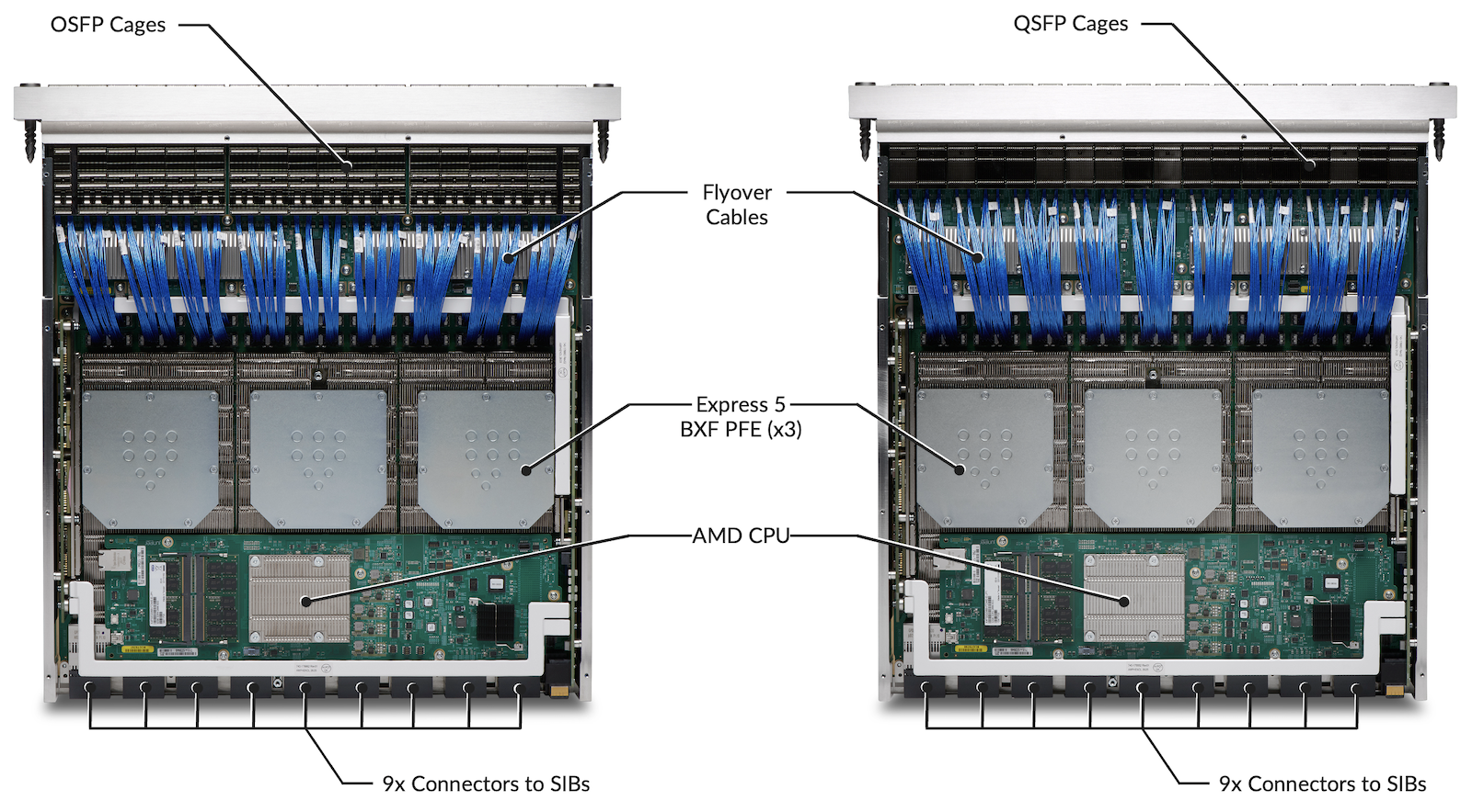
The cards can be positioned in any slot without any restriction, mixed and matched as you wish. Powered by three Express 5 BXF Packet Forward Engine for 43.2Tbps of forwarding capacity, they offer the highest port density per card in the industry: 54x 800Gbps ports (and yes, we mean real 800GbE here, but also 2x 400GbE, 8x 100GbE and many other channelization/breakout options).
They are hot removable and insertable, without any specific impact on the chassis. The use of a specific CLI "request chassis fpc slot X offline/online" is required for a smooth operation.
The benefits of such a unique hardware architecture and port density will be elaborated in dedicated blog posts. Without spoiling them nor going into too many details, I want to emphasize some key aspects:
It's a front-to-back cooling design, the cool air flow is received from the optics and goes towards the back of the chassis but also through the power shelf
All ports, QSFP or OSFP, can host high power 800G optics (ZR, ZR+). Cooling and power budget is designed to support all ports, on all slots, with 30W and 33W optics.
All ports can be encrypted at L2, line rate, with MACsec technology
The hardware guide will describe the cosmetics installation, cable management, etc.
Note that in normal operational conditions, the card is not equipped with ejector tool handles, they are only required for OIR (insertion/ejection). Here again, we invite you to carefully read the hardware guide for the exact procedure.
Considering the weight of the line cards (21kg of OSFP and 21.3kg and QSFP), we recommend two operators onsite or the use of specific lifting equipment to manipulate it.
The PTX12000 chassis can be populated with a maximum of 9 fabric cards named "PTX12008-SF" and "PTX12012-SF".
This number of fabric cards is required to offer the maximum possible bandwidth per PFE/Datapath, Chipset/Package and line card. Running the system with less than nine SIBs is fully supported and some commercial bundles rely on this capability (described later in " Running the chassis with less than 9x SIB" section). It's particularly useful if you don't need 43.2Tbps per slot.
The SIBs are inserted from the back of the chassis and occupy a central part in the design. They have 8 of 12 connectors to link to the line cards. Each fabric card is behind a fan tray, and it will be necessary to eject the fans first to insert/remove/replace a SIB.
SIB 0, 1 and 2 are behind Fan Tray 0
SIB 3, 4 and 5 are behind Fan Tray 1
SIB 6, 7 and 8 are behind Fan Tray 2
In these PTX12008-SF, you find 8x connectors to the cards, 6x retimers and 3x Express 5 BF ASICs (check figure 10 below). Each BF chipset can be seen as 144x144 crossbar with 106Gbps links and is designed to switch cells between the BXF PFEs.
Operating the system with nine or fewer fabric cards will have a linear impact on the forwarding capability of each PFE/DataPath.
It's essential to understand this aspect: if you are not consuming the entire bandwidth of a DataPath, the remaining forwarding capability is not dynamically re-allocated to a busier PFE. The number of available fabric cards equally impacts all PFEs. This comprehension is key when positioning the interfaces.
SIB
SIB BW per PFE/DP (in Tbps)
BW per slot (in Tbps)
9
7.2
43.2
8
6.4
38.4
7
5.6
33.6
6
4.8
28.8
5
4
24
4
3.2
19.2
3
2.4
14.4
2
1.8
9.6
1
0.8
4.8
Rule of the thumb: the 9 SIBs are necessary for line rate service, and each SIB lost will reduce linearly the forwarding capability by 11%.
Two options are available when ordering the system:
The Routing Engine (SKU: PTX12K-RE-BB/ PTX12K-RE-R) hosts the main compute capabilities of the chassis and centralizes most the control plane and management plane functions, on top of the supervision of the system itself.
Note: the slot in the chassis is marked "RCB" for Routing and Control Board and if the cards are name "RE" they are essentially RCBs.
Component
Description
CPU
Intel Icelake-D 10C @ 2.9GHz
DRAM
256GB DDR4 (4x 64GB DIMM)
SSD
2x 400GB NVMe drives
TPM
Yes, 2.0
Timing
HPE Juniper Timing FPGAConnectivity on the front:1PPS and 10MHz input and outputGPS 1pps input / outputG.703 TOD input portBITS (T1/E1) input / output1G SFP for GM port
This powerful CPU is used by various HPE Juniper software components leveraging multi-core capabilities. For example, Routing Process Daemon (RPD) supports multithreading to process routing updates and routing resolution.
The storage subsystem is comprised of 400GB solid-state drives (SSDs). Two are provided for redundancy, plus reliable management of the software upgrades and rollbacks. These drives are not field-replaceable.
The RE has enough storage, DRAM capacity, and CPU power to host 3rd party applications. Some of these applications may include custom Service Assurance Agents or statistics collection agents developed by HPE Juniper partners and customers. Even full Telegraf, InfluxDB, Grafana stack can run on the router itself for data collection and visualization, check out the blog post (https://juniper.github.io/techposts/telemetry-collector-and-dataviz-on-junos-evo/article).
From a security perspective, the RE is fully compliant with the TPM2.0 standard as published by the Trusted Computing Group (TCG). The TPM's non-volatile storage is used as a persistent, access-controlled area for component registration, location of policy, keys, etc.Trusted extensions are integrated into the Icelake CPU and only it can access the TPM. Hardware and firmware are designed to support FIPS 140-2 Level 2.
The first release supported on the PTX12008 is Junos Evo 26.2R1. Please reach out to your favorite HPE representative for more details. In Service Software Upgrade (ISSU) is not supported/planned.
The Routing Engine also hosts the control board, necessary for the internal operation of the entire chassis. The details are beyond the scope of this article, but we can say these functions guarantee the internal connectivity from the REs to all the components via an internal 10Gbps Ethernet switched network, but also via PCIe, and I2C networks. These networks are necessary to boot the system, transfer information between components but also monitor and control all conditions during the entire life of the router.
The different line cards have no LED and an operator on site can use the Front Panel Display to inspect the different parameters relative to the chassis, line cards and ports. It's just a display and it's not possible to configure anything or interfere with the operation of the router from this screen.
In a couple of click, it's possible to inspect the state of the different FRUs and ports of the system. A dedicated post will be published on the topic of the FPD navigation. Link will be added here soon.
Multiple fans are used to cool down and preserve the integrity of the system.
In each PSU active in the power shelf
In three fan trays installed vertically at the back of the router
These three PTX12008-FAN represent a total of 30 large fans operating simultaneously: 5 pairs of counter-rotating fans per tray (as shown in the output of the "show chassis fan" CLI below).
The PTX12012-FAN have a slightly different design, with 7 large single fans per tray.
Junos constantly collects and monitors dozens of temperature sensors scattered all around the chassis and adjust the rotation speed dynamically to maintain good operational environmental conditions.
root@ ptx12008-re0> show chassis environment monitored
Class Item                           Status     Measurement
Power PSM 0 Inlet Temp Sensor        OK         24 degrees C / 75 degrees F
      PSM 0 Connector1 Temp Sensor   OK         29 degrees C / 84 degrees F
      PSM 0 Connector2 Temp Sensor   OK         29 degrees C / 84 degrees F
      PSM 0 Outlet Temp Sensor       OK         43 degrees C / 109 degrees F

<SNIP>

root@ptx12008-re0> show chassis environment monitored | count
Count: 1329 lines

{master}

root@ptx12008-re0>
The system can operate with one faulty fan tray, the two others will be pushed to full speed. Therefore, it's possible to extract a fan tray in service to manipulate a SIB.
root@ptx12008-re0> show chassis fan
      Item                      Status   % RPM     Measurement
      Fan Tray 0 Fan 0          OK       56%       5700 RPM
      Fan Tray 0 Fan 1          OK       62%       7200 RPM
      Fan Tray 0 Fan 2          OK       55%       5550 RPM
      Fan Tray 0 Fan 3          OK       62%       7200 RPM
      Fan Tray 0 Fan 4          OK       55%       5550 RPM
      Fan Tray 0 Fan 5          OK       62%       7200 RPM
      Fan Tray 0 Fan 6          OK       55%       5550 RPM
      Fan Tray 0 Fan 7          OK       62%       7200 RPM
      Fan Tray 0 Fan 8          OK       56%       5700 RPM
      Fan Tray 0 Fan 9          OK       63%       7350 RPM
      Fan Tray 1 Fan 0          OK       56%       5700 RPM
      Fan Tray 1 Fan 1          OK       62%       7200 RPM
      Fan Tray 1 Fan 2          OK       55%       5550 RPM
      Fan Tray 1 Fan 3          OK       62%       7200 RPM
      Fan Tray 1 Fan 4          OK       55%       5550 RPM
      Fan Tray 1 Fan 5          OK       62%       7200 RPM
      Fan Tray 1 Fan 6          OK       55%       5550 RPM
      Fan Tray 1 Fan 7          OK       62%       7200 RPM
      Fan Tray 1 Fan 8          OK       56%       5700 RPM
      Fan Tray 1 Fan 9          OK       61%       7050 RPM
      Fan Tray 2 Fan 0          OK       56%       5700 RPM
      Fan Tray 2 Fan 1          OK       62%       7200 RPM
      Fan Tray 2 Fan 2          OK       55%       5550 RPM
      Fan Tray 2 Fan 3          OK       62%       7200 RPM
      Fan Tray 2 Fan 4          OK       56%       5700 RPM
      Fan Tray 2 Fan 5          OK       62%       7200 RPM
      Fan Tray 2 Fan 6          OK       55%       5550 RPM
      Fan Tray 2 Fan 7          OK       61%       7050 RPM
      Fan Tray 2 Fan 8          OK       55%       5550 RPM
      Fan Tray 2 Fan 9          OK       62%       7200 RPM

{master}
root@ptx12008-re0>
On the top of the router sits a power shelf. It's the same shelf whether we use AC or DC modules. On PTX12008, the shelf can host 20 power supply modules (4x5) while the 12-slot version can accommodate up to 36 units (4x9).
In the figure 14 below, we present the PTX12008 shelf with 20x 3kW DC modules on the left and with AC modules on the right, total 60kW.
These modules convert the grid energy into a 52V current that will be distributed among all the internal FRUs. Both provide dual feed connectors.
Note: The JNP-PWR-3K-AC and JNP-PWR-3K-DC modules are Power Supply Units shared with other product lines like the PTX10000. Also, we can NOT mix AC and DC in the same power shelf. It's one or the other.
The follow show commands provide an exhaustive view of the different PSMs, their feeds, but also the consumption of all internal components in real time (a lot of parts in the chassis, it's a long output).
The LC54s are based on a simple/optimized architecture in the sense the ports are fixed (no modularity requiring additional mechanical elements, connectors, power distribution, etc.) and their ports are directly connected to the NPU.
Each port is mapped to an individual Port Group, terminating 8x SerDes operated at speeds from 10Gbps (or 25Gbps) to 106Gbps depending on the pluggable present in the optical cage. We don't use any intermediate retimer/ReverseGearBox between the port and the forwarding engine or between the PFE and the fabric connectors.
The only difference between the QSFP and OSFP versions can be found in the mezzanine boards and of course the optical cages. The rest of the card architecture is common to the two types.
They host three BXF instances and each of them contains two datapaths seen as PFE 0 to 5 as shown below.
root@ptx12008-re0> show chassis fpc 0 detail
Slot 0 information:
  State                               Online
  Temperature                      51 degrees C / 123 degrees F (BX-0 HBM-0)
  Temperature                      52 degrees C / 125 degrees F (BX-0 HBM-1)
  Temperature                      50 degrees C / 122 degrees F (BX-1 HBM-0)
  Temperature                      49 degrees C / 120 degrees F (BX-1 HBM-1)
  Temperature                      52 degrees C / 125 degrees F (BX-2 HBM-0)
  Temperature                      52 degrees C / 125 degrees F (BX-2 HBM-1)
  Temperature                      49 degrees C / 120 degrees F (CPU)
  Total CPU DRAM                 65536 MB
  Start time                          2026-02-16 01:45:00 PST
  Uptime                              1 day, 9 hours, 48 minutes, 10 seconds
  Max power consumption           4900 Watts
  PFE Type                            Express-5

PFE Information:

 PFE  Power ON/OFF  Bandwidth         SLC
  0    On            7200
  1    On            7200
  2    On            7200
  3    On            7200
  4    On            7200
  5    On            7200

{master}
root@ptx12008-re0>
These line cards are not MPC per say (Modular PIC Concentrators), they are managed by the system as a single PIC, as displayed in the output below.
Note: it's possible to turn off and on one or two PFEs in the LC54 without impacting the service of the remaining one(s). This feature can be leverage in a power saving strategy.
A dedicated article will be published on the power aspect: the link will be updated here as soon as we will publish it.
The table below summarizes the interface's naming rules, including channelized ports.
All the ports follow the same rules based on the "Common Interface Configuration" model (CIC), regardless of their position in PICs.
Each physical port is mapped to a unique port group (PG) via 8x SerDes and no intermediate RGB, so we don't have any port combination limitation. You can use all ports with 2x400GigE or 8x100GigE without any constraint. Every port can be configured at the speed you need, but you can only support a unique speed for all members of the same physical port channelized (4x10GigE, 4x25GigE, 8x100GigE, 2x400GigE).
The port numbering on each line card is represented in the Figure 18 and 19 below:
The following illustrations describes the mapping between the ports' position, NPU, and DataPath.
With the bundle PTX12008-BASE (3x SIB, 1x RE, 12x PSM), the bandwidth available in each groups of 9 ports displayed above (PFE-0 or PFE-1, blue, green or purple) is reduced to 2.4Tbps total. It's doesn't mean you are limited to 3x 800GbE or 6x 400GbE optics: you can populate all 9 ports of the datapath. But the total bandwidth received or transmitted by all the interfaces of the DP will not exceed 2.4Tbps.
The complete list of supported interfaces will be updated soon on the Pathfinder; the following chart provides a couple of examples.
Port Type
#SerDes and Rate (Gbps)
#SerDes Effective Rate (Gbps)
800GigE
1x 800GAUI-8
8x 106.25
8x 100
400GigE
2x 400GAUI-4
4x 106.25
4x 100
400GigE
1x 400GAUI-8
8x 53.125
8x 50
200GigE
2x 200GAUI-4
4x 53.125
4x 50
100GigE
8x 100GAUI-1
1x 106.25
1x 100
100GigE
2x 100GAUI-4
4x 26.56254x 25.78125
4x 25
50GigE
2x LAUI-2
2x 25.78125
2x 25
40GigE
1x XLAUI
4x 10.3125
4x 10
25GigE
4x 25GAUI-1
1x 25.78125
1x 25
10GigE
1x XFI
1x 10.3125
1x 10
Note that we will interchangeably use the "effective bandwidth" (amount of WAN traffic from revenue ports) or the actual bandwidth of the SerDes (106.25/100 or 53.125/50 for example).
As a quick on-box reference, the following CLI command shows transceivers plugged into the port, plus the port speed capabilities (note: it shows capabilities and not necessarily the software support. Please use the port checker and hardware compatibility tools on apps.juniper.net to verify the support).
In a nutshell, QSFP ports can be configured from 10GbE to 800GbE while OSFP can be configured from 100GbE to 800GbE.
This article, despite its length, only scratched the surface of the PTX12000 chassis. We explored at high level the various FRUs, the interface configuration and some basic management functions. Many more articles will come complete it in the next weeks. Stay tuned...