Link Slicing with MPLS and SRv6 Underlays
Krzysztof Szarkowicz - 05/12/2023
The guaranteed link slicing feature, using MPLS and SRv6 as underlay transport.
Link slicing is a way to share physical bandwidth on links between multiple tenants, and guaranteed means providing minimum (guaranteed) bandwidth per tenant in case of congestion, as well as a possibility to enforce maximum transmit rates per tenant. Any leftover or unused bandwidth can be shared between tenants. Each slice can have own queue configurations for different classes of service within that slice.
This article is based on the capabilities of Junos 23.1R2 (or newer Junos release) running on MX Series routers. Configuration and operational command outputs have been collected on vMX and MX in our labs.
You can test yourself all the concepts described in this article, we created labs in JCL and vLabs: JCL (Junivators and partners) vLabs (open to all)
In this blog post, following IP (Internet Protocol) addressing is used:
Transport Infrastructure (P/PE)
- Router-ID: 198.51.100.
- Loopback: 2001:db8:bad:cafe:
00:: /128 - SRv6 locator: fc01:
: ::/48 - Core Links: 2001:db8:beef:
00:: : /112
PE-CE links:
- IPv4:
. . . /24 - IPv6: 2001:db8:babe:face:
:: : /112
VPN (Virtual Private Network) Loopbacks (CE/PE):
- 192.168.
. /32 - 2001:db8:abba:
:: /128
Architecture Introduction
The network topology and initial configuration used for this blog post is based on the network topology and configuration discussed in the SRv6 L3VPN Inter-AS Option-C blog post. That is, we have multi-domain network architecture with VRFs placed on the PE routers, and L3VPN over SRv6 Inter-AS Option-C framework to provide L3VPN connectivity between VRFs on the PEs in different domains. In addition to SRv6 Inter-AS Option-C, SR-MPLS Inter-AS Option-C has been added, so that link slicing for both MPLS and SRv6 underlays can be demonstrated. This is outlined in Figure 1.
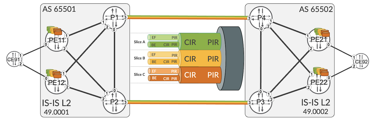
PE routers have multiple L3VPNs. Some of these VPNs use SRv6 as underlay (see the SRv6 SID Encoding and Transposition blog post for more details about L3VPN over SRv6), and some of these VPNs use SR-MPLS as underlay. Thus, both underlay types (SR-MPLS and SRv6) are used concurrently. This is a realistic scenario and might occur, for example, during migration from MPLS to SRv6 underlay.
Nevertheless, focus of this blog post is not the discussion about nuances of concurrent running of SR-MPLS or SRv6 underlays. Focus of this blog post is link slicing, and both underlays are simply used to illustrate that link slicing can work with both MPLS (any type of MPLS, not only SR-MPLS) and SRv6.
Link Slicing Introduction
Before going into configuration or operational commands details, let's discuss the use case: what is a "link slicing", where and how we could use link slicing?
Link slicing is a specific use case under overall umbrella called "network slicing". With link slicing, you slice (channelize, partition, divide, ... -- use the word you like) a single link is such a way, that each slice has explicit capacity guarantee, and each slice can have multiple traffic classes and queues. For example, Flexible Ethernet (FlexE) is a technology that allows to channelize an Ethernet link, with fixed bandwidth guarantees for each channel.
Saying that, FlexE might not be the best technology for link slicing/channelization. The major drawbacks of FlexE, when used for link slicing/channelization are:
- no statistical multiplex gain/no bandwidth reuse between channels
- requires large physical links (50 Gbps and above) with large b/w increments (5 Gbps)
- requires an underlying electrical transport switching layer to support channelization
Therefore, to overcome the drawbacks associated with FlexE, this blog post uses different approach for link slicing, utilizing hierarchical QoS (H-QoS) toolset. Traditional, legacy H-QoS architecture is depicted in Figure 2.
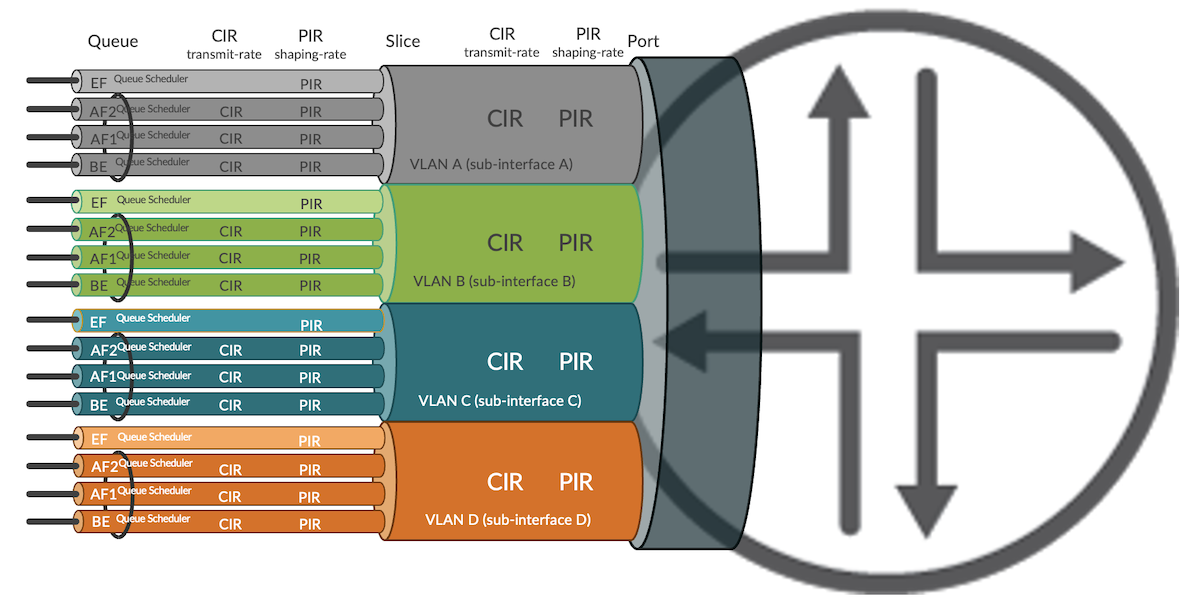
In this architecture the link is divided into subinterfaces (units in Junos terms), where each subinterface is associated with a VLAN. The QoS profile (traffic control profile in Junos terms) contains QoS parameters for each subinterface, like:
- CIR (Committed Information Rate) -- guaranteed minimum rate
- PIR (Peak Information Rate) -- maximum (shaping) rate
- Queue parameters inside each profile, with queue priorities, queue sizes, minimum/maximum rate of each queue, etc.
We could reuse this model for link slicing -- theoretically at least. So, why we don't do it? What is the problem with this model?
Well, if you look at Figure 1, the depicted use case for link slicing is to slice inter-AS link (please note, this is just an example; there could be many other use cases calling for link slicing at different locations in the network). With traditional H-QoS approach for link slicing, it would mean considerable administrative overhead:
- VLAN allocation and co-ordination between two domains
- IP addressing for each subinterface allocation and co-ordination between two domains
- In case of intra-domain link slicing, multiple IGP adjacencies would need to be started to make the subinterfaces usable for traffic
- In case of inter-domain link slicing, multiple eBGP peerings, and/or import/export BGP policies with next-hop manipulation to make the subinterfaces usable for traffic
This might become complex task, especially, if the use case demands slicing on multiple links.
Link Slicing with Slice-Aware H-QoS
To address this complexity, starting from Junos 22.2R1, Juniper successively began to introduce features allowing H-QoS deployments for link slicing in much simpler manner (slice-aware H-QoS). This blog post uses features available from Junos 23.1R2.
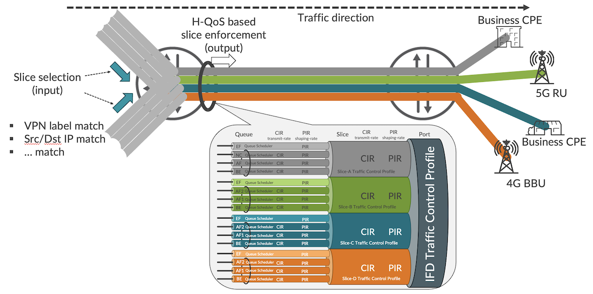
In essence, slice-aware H-QoS uses abstract objects called 'slices' to attach QoS profiles on the link. So, no subinterfaces, VLANs, multiple IP addresses, multiple IGP/BGP sessions on the link are longer required, as with traditional H-QoS model. This simplifies operations and does not affect packet forwarding in any way.
When packets enter the router, they are classified as belonging to a specific slice. Packets not classified explicitly, are associated with a default slice. Packet classification, implemented with firewall filter, can happen practically based on any existing field in the packet, like for example top MPLS label, bottom MPLS label, Src/Dst IP address, some specific bits from Src/Dst IP address, etc.
When the packet leaves the router on sliced link, packets are subject to the treatment defined in the slice-specific QoS profile, based on the slice selection performed on input.
Slice-Aware H-QoS Configuration
In the topology depicted in Figure 1, link slicing is configured on inter-AS links. As an example, configuration of P1 router will be discussed.
First, the slices must be initialized, as outlined in Configuration 1. As an example, we will be using 3 slices, called NS-A, NS-B and NS-C, to illustrate link slicing capability.
Configuration 1: Slice initialization
Second, hierarchical scheduler capability on the sliced interface must be enabled, as outlined in Configuration 2. Please note, up to Junos 23.1R1 enabling hierarchical scheduler is possible only on interface divided into subinterfaces (VLANs), to support classical H-QoS. Junos 23.1R2 removes that restriction, allowing enabling hierarchical scheduler capability on plain (not divided to subinterfaces) interfaces as well, for slice-aware H-QoS support.
Configuration 2: Enabling H-QoS capability
Now, QoS configuration must be prepared, with QoS profiles attached to the slices on the interface. This blog post does not intent to cover Junos QoS in details, as this is a huge topic. Therefore, to demonstrate slicing capability, relatively simple QoS configuration is used, as outlined in Configuration 3:
1 2 3 4 5 6 7 8 9 10 11 12 13 14 15 16 17 18 19 20 21 22 23 24 25 26 27 28 29 30 31 32 33 34 35 36 37 38 39 40 41 42 43 44 45 46 47 48 49 50 51 52 53 54 55 56 57 58 59 60 61 62 63 64 65 66 67 68 69 70 71 72 73 74 75 76 77 78 79 80 81 82 83 84 85 86 87 88 89 90 91 92 93 94 95 96 97 98 99 100 101 102 103 104 | |
Configuration 3: Slice-aware H-QoS
The main aspects of this sample QoS configuration are as follows:
- Two forwarding classes -- FC-BE and FC-EF -- (lines 28-31). Please note, this is only example. Each slice can support up to 8 forwarding classes.
- DSCP and MPLS TC classifiers to classify packets into the forwarding class based on DSCP or MPLS TC values in the packet (lines 2-27). Additionally, classifiers are assigned to the interfaces (lines 53-61).
- Traffic control profiles -- per port and per slice profiles -- (lines 32-51). Per slice profiles have some example minimum (guaranteed) rates and maximum (shaping) rates. Additionally, traffic control profiles is attached to the sliced interface (lines 62-73), resulting in H-QoS hierarchy depicted in Figure 1.
- Traffic control profiles reference scheduler maps (lines 37, 42, 47, 75-88), which define queue parameters for each slice via schedulers (lines 89-103). In this simple example, each slice uses the same queue parameters for simplification. However, in the production deployment, each slice can be parametrized differently, based on the actual requirements.
As the result of the QoS configuration, we have three slices as follows:
| Slice Name | min BW | max BW | Queues |
|---|---|---|---|
| NS-A | 50 Mbps | 100 Mbps | FC-EF: strict-high, 50% (rate limited)FC-BE: low, remaining slice BW |
| NS-B | 5 Mbps | 5.6 Mbps | FC-EF: strict-high, 50% (rate limited)FC-BE: low, remaining slice BW |
| NS-C | 4 Mbps | 5.1 Mbps | FC-EF: strict-high, 50% (rate limited)FC-BE: low, remaining slice BW |
Table 1: Slice QoS profiles
Based on the configuration done so far, initial checks can be performed (CLI-Output 1). Please note, based on the MX line card used, the output of the operational command might be slightly different.
1 2 3 4 5 6 7 8 9 10 11 12 13 14 15 16 17 18 19 20 21 22 23 24 25 26 27 28 29 30 31 32 33 34 35 36 37 38 39 40 41 42 43 44 45 46 47 48 49 50 51 52 53 54 55 56 57 58 59 60 61 62 63 64 65 66 67 68 69 70 71 72 73 74 75 76 77 78 79 80 81 82 83 84 85 86 87 88 89 90 91 92 93 94 95 96 97 98 99 100 101 102 103 104 105 | |
CLI-Output 1: Initial check for slice NS-A
We can see counters of queues for slice NS-A (counters of queues for slice NS-B and NS-C are not shown for brevity). At the moment, all counters are '0', despite the traffic already flows through the network (traffic generators generating traffic are attached to CE devices). The reason is, the current configuration defines slices, slice QoS profiles, and assigns slice QoS profiles to the interface. However, the current configuration doesn't assign traffic to slices, so at the moment all traffic is using default slice only.
Depending on the MX hardware used, it might happen -- especially on older MX line cards -- that configuration discussed so far is not sufficient to enable slice-aware H-QoS (CLI-Output 2).
CLI-Output 2: Failed initial check for slice NS-A
In such situation, additional configuration (enabling egress traffic manager and/or enabling flexible queueing mode) might be required (Configuration 4).
Configuration 4: Enhanced QoS
Assigning Traffic to Slices -- MPLS
Assigning traffic to appropriate slice is a multiple step process.
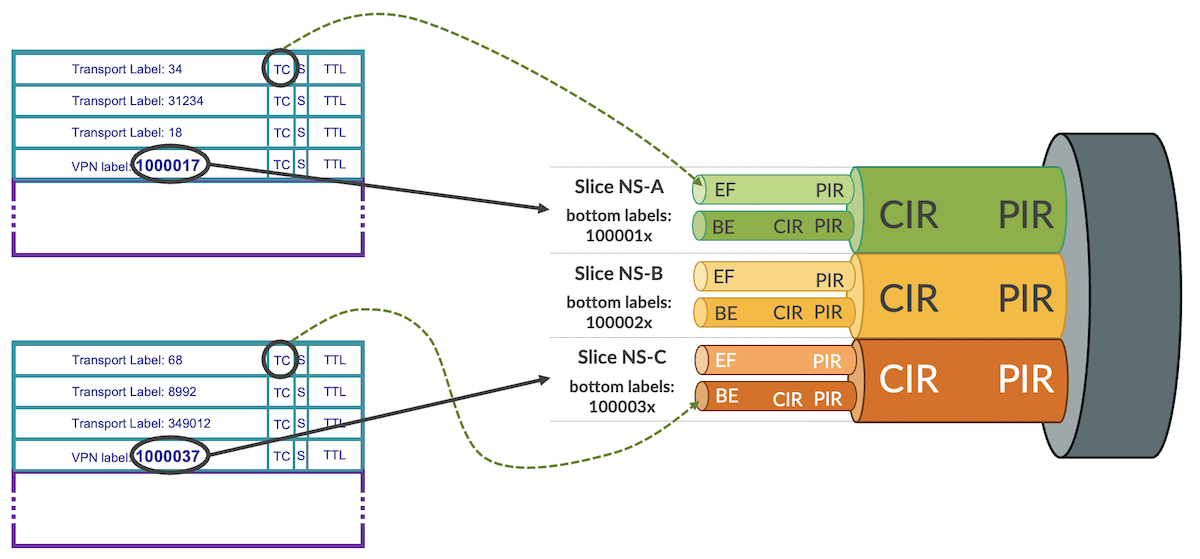
First of all, there must be common agreement in the network, which fields in the packet will be used for slice identification. For MPLS based underlay the obvious choice is MPLS label. The Junos framework for link slicing is very flexible, allowing MPLS labels (or label ranges) at any position (e.g., top, bottom with/without offset from top/bottom) in the label stack to be used for slice identification purposes.
In this blog post L3VPN labels, which will be present at the bottom of the label stack (SR-TE or TI-LFA could use multiple transport labels above bottom service label) in the packet, will be used for slice identification, as depicted in Figure 4.
Following L3VPN label ranges are used in this blog post (again, this is just simple example -- Junos link slicing framework doesn't put any restrictions here):
| Slice Name | Min Label | Max Label |
|---|---|---|
| NS-A | 1000010 | 1000019 |
| NS-B | 1000020 | 1000029 |
| NS-C | 1000030 | 1000039 |
Table 2: Slice MPLS service (bottom) label ranges
The selected label ranges are from the default Junos range used for static labels, as outlined in CLI-Output 3, lines 11 and 17.
CLI-Output 3: MPLS label ranges
L3VPN service labels are of local significance, and can be re-used on every ingress PE independently. This is important for scaling. If for a particular deployment different MPLS label ranges should be used for slice identification (e.g., in multi-vendor environment, when 3rd party equipment cannot use range 1000000-1048575 for static label), the static label range could be changed with 'set protocols mpls label-range' command. This blog post uses default static label range.
Now, when the VRFs are orchestrated on PE routers, they must be orchestrated with appropriate VRF labels (Configuration 5).
Configuration 5: Label assignment to VRFs
With this configuration, traffic of VRF17 will use service (bottom) label 1000017, traffic of VRF27 will use service (bottom) label 1000027, and traffic of VRF37 will use service (bottom) label 1000037. This corresponds to the MPLS label ranges defined in Table 2.
When the packets arrive to P1, which is agnostic to existing VPNs, but should perform slicing on inter-AS links, packets can be classified to slices based on the bottom label ranges (Configuration 6). Multiple label ranges can be specified in a single match term.
Configuration 6: Classification to slices based on bottom MPLS label
It is a pretty simple configuration. Firewall filter matches for bottom label ranges (lines 31-35, 43-47, 55-59), and assigns packets to appropriate slice (lines 37, 49, 61). MPLS packets not matched (bottom label not within specific range) are kept in the default slice. Subsequently, the firewall filter is used as input filter on the core interfaces (lines 1-26).
Quick verification confirms that packets are now classified by the filter to slices (CLI-Output 4).
CLI-Output 4: Slice classification based on MPLS
When we now check the queue status of each slice, we see now some counters (CLI-Output 5):
1 2 3 4 5 6 7 8 9 10 11 12 13 14 15 16 17 18 19 20 21 22 23 24 25 26 27 28 29 30 31 32 33 34 35 36 37 38 39 40 41 42 43 44 45 46 47 48 49 50 51 52 53 54 55 56 57 58 59 60 61 62 63 64 65 66 67 68 69 70 71 72 73 74 75 76 77 78 79 80 81 82 83 84 85 86 87 88 89 90 91 92 93 94 95 96 97 98 99 100 101 102 103 104 105 106 107 108 109 110 111 112 113 114 115 116 117 118 119 120 121 122 123 124 125 126 127 128 129 130 131 132 133 134 135 136 137 138 139 140 141 142 143 144 145 146 147 | |
CLI-Output 5: Verification of slice-aware H-QoS
We see around 2 Mbps of traffic in each slice, with 1 Mbps in each forwarding class in each slice (remaining two forwarding classes in each slice are not used in this example, therefore not shown for brevity). All traffic is passing through without any drops, as there is no congestion on the link (so, guaranteed rate doesn't matter), and all slices are within their maximum rate limits (thus, no shaping happens).
This looks good.
Now, let's add some more traffic to the picture.
Assigning Traffic to Slices -- SRv6
This time, let's add SRv6 traffic. And yes, the same link slice can carry different traffic types. We can mix both MPLS and SRv6 flows within the same slice, and apply common QoS guarantees and constraints for such mixed slice. Junos link slicing framework is very flexible.
The process of assigning traffic to slices is similar to MPLS at the high-level. However, this time we don't have MPLS labels, but SRv6 SIDs (see SRv6 SID Encoding and Transposition blog post (and earlier SRv6 blog posts), SRv6 SID is a 128-bit long data structure, divided into Locator:Function:Argument fields. The division is flexible, and each field can be further decomposed to carry various information.
One example of the of SRv6 SID allocation scheme, used in this blog post, is presented in Figure 5.

4 bits in the SRv6 locator are used for AS (Domain ID), 16 bits are kept for Node ID. Function as well has designated bits for slice ID (4 bits) and VPN ID (16 bits). Please remember, it is just an example. Depending on the actual use case and requirements, Locator:Function space can be arranged in different ways. For example, slice ID could be part of the SRv6 Locator, not part of Function.
Figure 6 shows the slice selection based on slice ID encoded in SRv6 SID.
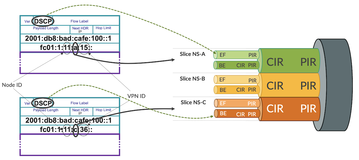
Base configuration for SRv6 Locator and End SID on PE11 is outlined in Configuration 7. There is nothing really new here, when compared to previous SRv6 blog posts.
Configuration 7: Base SRv6 Locator and End SID
Now, the interesting part is the SRv6 End.DT46 SID allocation (Configuration 8).
Configuration 8: SRv6 SID End.DT46
There are six VPNs defined, two for each slice -- note 'a', 'b' and 'c' in the SID Function part (lines 8, 21, 34, 47, 60, 73), which is the agreed slice ID. Behind slice ID, you can see VPN ID (note VPN IDs: 15, 16, 25, 26, 35, 36).
Now, when the packets are sent with SRv6 encapsulation (essentially IP in IPv6 encapsulation), the destination address of the outer IPv6 header is equal to the SRv6 End.DT46 SID. Therefore, on P1 router, we need to match for specific bits encoding slice ID in the destination address of the packet, to classify the packet to a particular slice. For this, it is helpful to understand the IPv6 header structure (Figure 7).
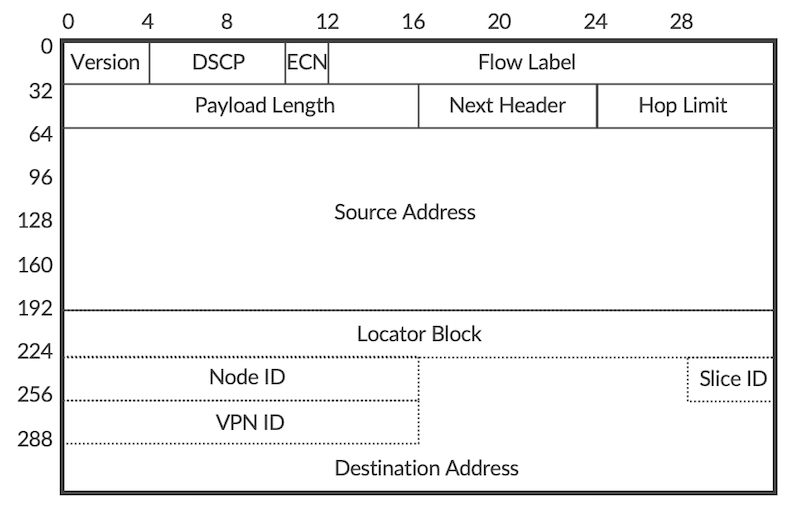
Initial fields from IPv6 header occupy 64 bits, source address is 128 bits, which gives 192 bits. When looking at the Figure 5, we can observe that SRv6 Locator occupies additional 48 bits (32 bits locator block +16 bits node ID), and most left byte (8 bits) from function is not used. This gives us in total 192 + 48 + 8 = 248 bits, or 31 bytes. Therefore, in order to match for slice ID, we will need to match 32nd byte in the IPv6 header.
To match the slice ID on P1 router we will use firewall filter with flexible match condition. This filter provides great flexibility, practically allowing to match any particular bits in the packet header (Configuration 9).
Configuration 9: Classification to slices based on SRv6 slice ID
Lines 80-85 define the flexible match mask, which essentially is the location in the packet, where our match should be performed. In this particular case, the match will be performed in the 32nd byte (byte offset 31, i.e., we are skipping first 31 bytes) of layer 3 header. This flexible match mask is then used in the IPv6 firewall filter so, the layer 3 header becomes IPv6 header (lines 45, 49, 63). The filter has further mask to narrow down the match to last 4 bits (lines 33, 47, 61) within the byte selected by flexible match mask. And, we are looking for specific values -- 0xa, 0xb and 0xc -- in these 4 bits (lines 34, 48, 62) to assign packets to specific slices (lines 39, 53, 67). Similar to MPLS filter, this IPv6 filter is applied as input filter on core interfaces (lines 1-26).
Before performing any verification, let's summarize current configuration state:
- Slice-aware H-QoS (link slicing) configured on inter-AS link, with three slices having different min/max bandwidth constraints, each slice with two forwarding classes
- 9 VRFs on PE routers, 3 VRFs per slice. Within each slice, 2 VRFs use SRv6 as underlay and 1 VRF uses MPLS as underlay
- Traffic generators send traffic with traffic rate 2 Mbps per VRF with two forwarding classes (1 Mbps per forwarding class)
- So, we have in total 6 Mbps per slice (3 Mbps per forwarding class in each slice)
- Each slice on inter-AS link has mixed SRv6 and MPLS traffic
Now, let's check the statistics for both MPLS and SRv6 based slice classification (CLI-Output 6).
CLI-Output 6: Slice classification based on SRv6 slice ID
We can observe that both MPLS and IPv6 (SRv6) traffic is assigned to the slices. For IPv6 traffic we have small amount not assigned to any particular slice -- this is control traffic (e.g. BGP), which is not matched explicitly in the firewall filter. The default slice has by no guarantees by default, so in the real-life deployment, it is recommended to assign control traffic to a separate 'control plane' slice, with some guarantees (1-5% of link capacity) to avoid suppression of control plane traffic by other slices. Alternatively, some guarantees can be provided to the default slice, by attaching appropriate traffic control profile to remaining queues on the interface ('set class-of-service interfaces
Now, checking the slice queue statistics we can make interesting observations (CLI-Output 7).
1 2 3 4 5 6 7 8 9 10 11 12 13 14 15 16 17 18 19 20 21 22 23 24 25 26 27 28 29 30 31 32 33 34 35 36 37 38 39 40 41 42 43 44 45 46 47 48 49 50 51 52 53 54 55 56 57 58 59 60 61 62 63 64 65 66 67 68 69 70 71 72 73 74 75 76 77 78 79 80 81 82 83 84 85 86 87 88 89 90 91 92 93 94 95 96 97 98 99 100 101 102 103 104 105 106 107 108 109 110 111 112 113 114 115 116 117 118 119 120 121 122 123 124 125 126 127 128 129 130 131 132 133 134 135 136 137 138 139 140 141 142 143 144 145 146 147 148 149 150 151 152 153 154 155 156 157 158 159 160 161 162 163 164 165 | |
CLI-Output 7: Verification of slice-aware H-QoS
There are no drops in slice NS-A. In slice NS-B we observe small drops in forwarding class FC-BE. In slice NS-C we observe even bigger drops, but again in forwarding class FC-BE only. The observations are in line with the expectations (please refer to Table 1 for slice rates). Also, for slices observing drops, only FE-BE class, with low priority, is affected. Strict-priority FC-EF class is not affected.
Next Steps
In the next blog post we will show another slicing use case with lookup entry assigning packets to slices, instead of firewall filter based assignment.
Useful links
- Firewall Filter Flexible Match Conditions: https://www.juniper.net/documentation/us/en/software/junos/routing-policy/topics/concept/firewall-filter-flexible-match-conditions-overview.html
- Slice (firewall filter action): https://www.juniper.net/documentation/us/en/software/junos/cos-hierarchical/cos/topics/ref/statement/slice(firewallfilteraction).html
- Slice-aware H-QoS: https://www.juniper.net/documentation/us/en/software/junos/cos-hierarchical/cos/topics/topic-map/HierarchicalCoSqueuingforsliceper-hop-behavior.html
- TechPost 1: SRv6 Basics Locator and End-SIDs - https://juniper.github.io/techposts/srv6-basics-locator-and-end-sids/article
- TechPost 2: L3VPN on SRv6 - https://juniper.github.io/techposts/l3vpn-over-srv6/article
- TechPost 3: SRv6 Summarisation - https://juniper.github.io/techposts/srv6-summarization/article
- TechPost 4: SRv6 SID Encoding and Transposition - https://juniper.github.io/techposts/srv6-sid-encoding-and-transposition/article
- TechPost 5: SRv6 L3VPN Inter-AS Option-C - https://juniper.github.io/techposts/srv6-l3vpn-inter-as-option-c/article
- TechPost 6: Link Slicing with MPLS and SRv6 Underlays - https://juniper.github.io/techposts/link-slicing-with-mpls-and-srv6-underlays/article
- TechPost 7: Link Slicing with MPLS and SRv6 Underlays Part 2 - https://juniper.github.io/techposts/link-slicing-with-mpls-and-srv6-underlays-part-2/article
Glossary
- AS: Autonomous System
- ASBR: Autonomous System Boundary Router
- BGP: Border Gateway Protocol
- BW: Bandwidth
- CE: Customer Edge
- CIR: Committed Information Rate
- CLI: Command Line Interface
- DSCP: Differentiated Services Code Point
- Dst: Destination
- eBGP: external Border Gateway Protocol
- ECN: Explicit Congestion Notification
- FlexE: Flexible Ethernet
- Gbps: Gigabits per second
- H-QoS: Hierarchical Quality of Services
- iBGP: internal Border Gateway Protocol
- ID: Identifier
- IGP: Interior Gateway Protocol
- Inter-AS: Inter Autonomous System
- IP: Internet Protocol
- IPv4: Internet Protocol version 4
- IPv6: Internet Protocol version 6
- IS-IS: Intermediate System to Intermediate System
- L2: Level 2
- L3VPN: Layer 3 Virtual Private Network
- Mbps: Megabits per second
- MPLS: Multiprotocol Label Switching
- NHS: Next Hop Self
- OSPF: Open Shortest Path First
- P: Provider
- PE: Provider Edge
- PIR: Peak Information Rate
- PSP: Penultimate Segment Pop
- QoS: Quality of Services
- RFC: Request for Comments
- RIB: Routing Information Base
- RR: Route Reflector
- SID: Segment Identifier
- SR: Segment Routing
- Src: Source
- SR-MPLS: Segment Routing with Multiprotocol Label Switching
- SR-TE: Segment Routing Traffic Engineering
- SRv6: Segment Routing version 6
- TC: Traffic Class
- TI-LFA: Topology Independent Loop Free Alternates
- TLV: Type Length Value
- USD: Ultimate Segment Decapsulation
- USP: Ultimate Segment Pop
- VLAN: Virtual Local Area Network
- VPN: Virtual Private Network
- VRF: Virtual Routing and Forwarding
Acknowledgements
Many thanks to Anton Elita for his thorough review and suggestions, and Aditya T R for preparing JCL and vLabs topologies.