MNHA, IPSec and Multiple Routing Instances
Introduction
There is a lot of good documentation available on designing and implementing MultiNode High Availability (MNHA) and Virtual Private Networks (VPNs) on SRXs - even AI generated configuration snippets that might lead a novice or experience professional astray. AI is a wonderful tool, but who hasn't been a little frustrated by some AI output that includes commands or configuration recommendations that aren't available on the platform.
This post is not intended to be a 100% exhaustive guide on designing or configuring MNHA or VPNs with SRX deployments. The goal is to provide working solutions with explanations and call-out caveats relative to MNHA as well as with VPN deployments. Starting with a review of the fundamentals, then building to common deployments for remote access and site-to-site VPNs with a more holistic, integrated focus, not just spot configurations.
Of course, it goes without saying, "Mileage varies...". The examples may fit some potential uses cases well, however, there may also be additional complexities not optimal for certain production environments. This content is intended to align with a planning motion to aid in understanding aspects of MNHA related to common IPSec implementations. When in doubt, document, document, document and follow one of the best design principles, keep the design as simple as possible to meet the requirements without adding undue complexity.
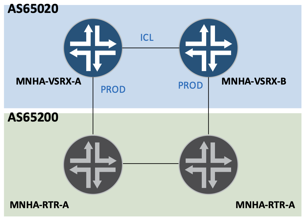
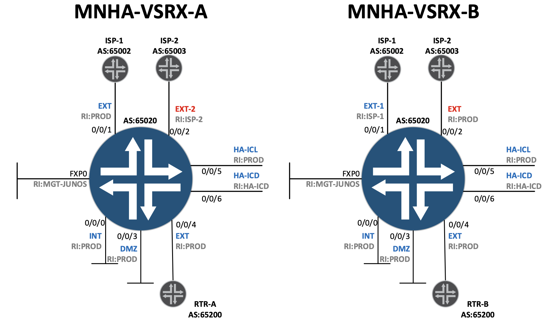
The figure below will represent the high-level topology-- incorporating a pair of SRX with two different ISP connections and an Extranet (or partner) connection.
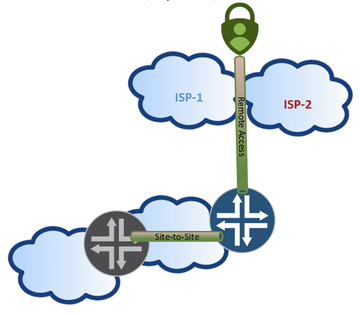
Focus will be centric considering flows and impacts incorporating diverse upstream providers and redundant ISP connections creating the classic "bow-tie" design. Initially this added level of redundancy may seem appealing, from a routing, connectivity point of view. SRXs deployed as security devices have more rigid requirements when processing flows than just routing packets. When you get to the "Keeping it Simple" section, with the topology we'll discuss, you'll probably realize that those extra redundant connections are just for show, added complexity and no real function. During that journey from here to there, the main topics and observations that will be covered throughout include:
- SRX Fundamentals
- Inclusion of multiple routing instances
- MNHA
- ICD and Asymmetric flows
- Network Address Translations (NAT) implications
- IPSec VPNs
This post assumes familiarity with MNHA fundamentals. If you're new to MNHA or need a refresher, do yourself a favor and read these first, in order:
-
- Multi-Node High Availability Basics: Steven Jacques covers the foundational concepts: ICL mechanics, SRG0, Active/Warm session synchronization, and config sync via Junos groups. If those terms aren't familiar, start here.
-
- Hybrid MNHA with eBGP: covers hybrid deployment mode, BFD-driven failover, signal routes, and MED-based BGP traffic engineering. The topology in this post builds directly on those concepts.
-
- SRX clustering: from Chassis Cluster to MultiNode High Availability: Laurent Paumelle's architectural overview of MNHA modes, SRG taxonomy, and platform support. Good context if you're evaluating MNHA or migrating from Chassis Cluster.
This post doesn't repeat what those cover. The intent is to build on them, not restate them. Consider this your homework assignment before diving in.
Foundations
It's imperative to have a strong grasp of the basic building blocks of the SRX beyond security policies to have a successful MNHA deployment. While it may seem obvious in certain green-field deployments, migrating or adding MNHA in an existing deployment may provide some challenges and potential redesign to glean the benefits.
The topology used represents a pair of MNHA clustered SRX in the center with two northbound connections to separate ISP providers where hosts will use remote access VPN, a protected "DMZ" and internal subnets, south bound connections to additional internal networks including Extranet/partner site-to-site VPN connections.
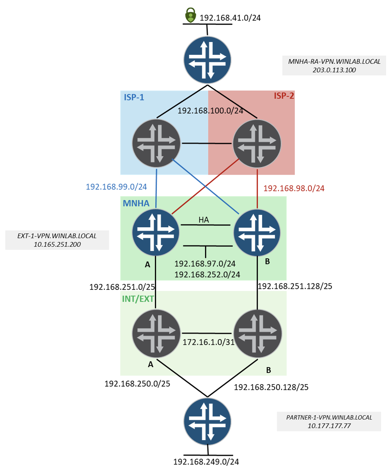
For readability, in-line example configurations may omit additional statements. Refer to complete configurations located at the end of this post.
SRX
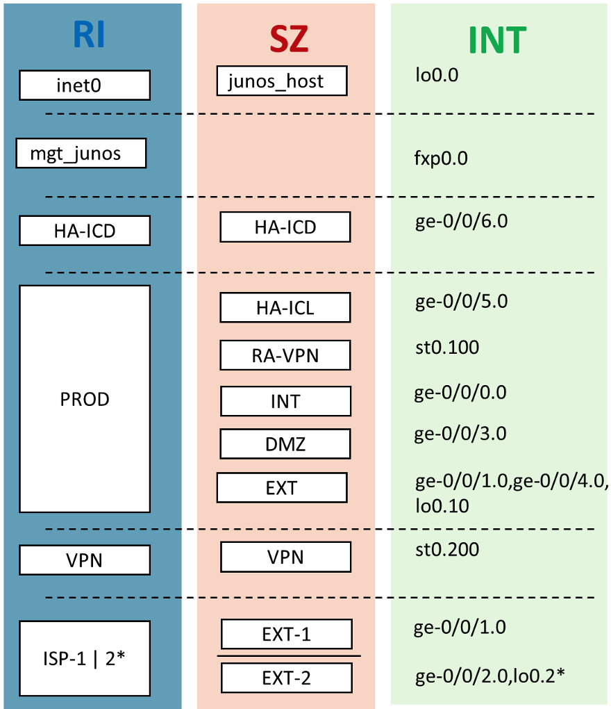
- Interfaces are mapped to security zones.
- Interfaces also map to routing instances.
- You cannot have an interface assigned to more than one zone or routing instance. This includes loopback interfaces.
Why is this an important? Consider if you have multiple routing-instances and you want to configure MNHA, leveraging a loopback interface as your external interface for anchoring VPNs. The concept of IKE Gateway lookups is from the perspective where the Inter Chassis Link (ICL), what routing instance, it is configured in. More on this later...
Mapping routing instances (RI), security zones (SZ) and interfaces (INT) in Figure 3 may seem like excessive segmentation but the level segmentation used is to highlight operational dependencies and flexibility.
Interfaces
Reiterating, the purpose of this post is to illustrate features/functionality and doesn't constitute best practices for network design/placement of organizational elements or resources. Explanation of the interfaces and function for the lab simulation follows:
Public (ISP) connections:
- GE-0/0/1 - L3 ISP-1 connection with single-hop BGP peering (192.168.99.0/24).
- GE-0/0/2 - L3 ISP-2 connection with multi-hop BGP peering (192.168.98.0/24).
Private "DMZ" subnets, directly connected to the SRXs without any additional L3 hops.
- GE-0/0/0, Source NAT pools required to reach public resources (192.168.252.0/24).
- GE-0/0/3 - Static NAT required for access from public or private connections (192.168.97.0/24).
Additional private internal connections. Routed connectivity representing a larger internal network. This is where connectivity for the site-to-site VPNs exists.
- GE-0/0/4, L3 BGP connected (192.168.251.0/25 (SRX-A) and 192.168.251.128/25 (SRX-B))
MNHA
- GE-0/0/5, ICL (100.64.0.0/27)
- GE-0/0/6, ICD (100.64.10.0/27)
It is recommended to use redundancy for the ICL/ICD interfaces. These L3 interfaces are not required to be directly connected. In this topology, they are simply directly connected single interfaces providing L3 functionality between the two SRXs.
Secure Tunnel Interfaces
- ST0.100, supporting remote access VPN connections.
- ST0.200, Site-to-Site (S2S) VPN
Loopback interfaces
- Loopback0.0, used for self-traffic originating default traffic from inet0. Unique per SRX:
10.0.0.33/32 = SRX-A
10.0.0.44/32 = SRX-B - Loopback0.2, used for eBGP multi-hop peering from SRX-A to ISP-2, 10.12.12.12/32. - Loopback0.10, multi-purpose, primarily used for "floating-IP" addresses used with MNHA and eBGP peering. Floating addresses are configured identically on both SRXs.
10.13.13.13/32 - used for eBGP multi-hop peering from SRX-B to ISP-2
203.0.113.100/32, used for anchoring remote access VPN connections
10.165.251.200/32, used for anchoring site-to-site VPN connection(s).
For those unfamiliar with loopback interfaces in JUNOS - the loopback interface is a logical interface. It appears to the system that only one loopback interface available - Loopback0; unlike other platforms where you can create many logical loopback interfaces, assigning them different identifiers and associated IP addresses. To achieve similar results with the SRX, you carve up the loopback interface with different unit numbers, e.g. sub-interfaces. You can assign multiple IP addresses to each of the different units. However, only 1 loopback (sub-interface) can be configured in a routing-instance (1:1 relationship).
Interface configurations for MNHA-VSRX-A
Interface configurations for MNHA-VSRX-B:
Security Zones
Security zones form logical groups that we associate with security policies to provide granular protections. Security zones are especially important when creating VPNs and anchoring them with floating IPs (loopback interfaces). Why? Because the loopback interface and the physical interface used for the VPN connections are required to be in the same security zone. Additional details provided in the VPN section.
For this environment, let's clarify the EXT and EXT-1 | 2 variant zones. The EXT-1 and EXT-2 security zones are 100% associated with our ISP traffic; no other interfaces explicitly configured other than required for connectivity via the ISP uplinks. Not the case with the EXT zone. There is a constraint of having the floating-ip for anchoring VPN connections to be in the same RI as the MNHA ICL link as well as an additional constraint of having the loopback and physical interfaces for VPN terminations to be the same zone.
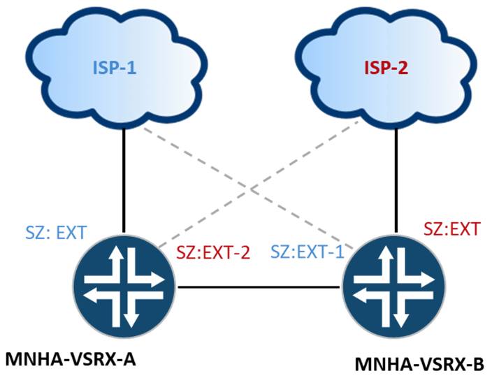
There is no requirement to have different zone names between the variant EXT-1 and EXT-2 zones, for illustration purposes only, the security zones EXT-1 align with "ISP-1" and EXT-2 with "ISP-2". A variation could be something like ALT-ISP(RI) and ALT-ISP(SZ) on both SRXs.
Security Zone Configurations:
Routing Instances
Routing instances create isolated Layer 3 routing constructs. Common use cases include segmentation methods for overlapping/duplicate IP addresses, multi-tenancy, and macro segmentation for different networks. You may want to just keep it simple and have a single routing table (e.g. inet0) for all forwarding decisions.
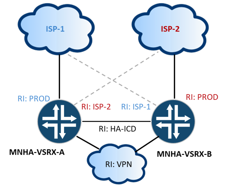
Mgmt_junos is to isolate management traffic from other traffic types; doesn't support transit traffic. Inet0 is used for self-traffic by default. Connecting to services for antimalware, antivirus, DNS queries, etc. By default, all traffic is permitted in and out of the junos-host zone that passes the host-inbound-traffic settings applied to each security zone. Additional security policies specifying junos-host as a source or destination zone can be applied for additional security controls.
- HA-ICD, separates the ICD traffic from other routing instances.
- PROD, routing table supports most of the interfaces and security zones including one of the two ISP connections. ISP connections are L3 separated for control and support for NAT scenarios.
- VPN, additional RIs like VPN aren't a requirement to keep flows isolated while crossing security zones. This is easily accomplished with applicable security policies.
- ISP-1/ISP-2, discrete routing tables used for connecting with ISP-1 or ISP-2.
Routing Instance Configurations
VPN
There is plenty of great documentation for the myriad of configuration settings available under the VPN umbrella. With that said, here is a high-level review of the basic steps required to configure IPSec VPNs on SRX:
Reviewing the steps required to configure IPSec VPNs on SRX:
- Interfaces and Security Zones
- Phase 1, IKE Proposals, IKE Policies and IKE Gateway (external interface)
- Phase 2, IPSec Proposals, IPSec Policies, binding VPN tunnel interface (ST0) and IKE gateway, and specifying interesting traffic to route and encrypt across the tunnel.
- Authentication, Address Pools, etc.
- Security Policies
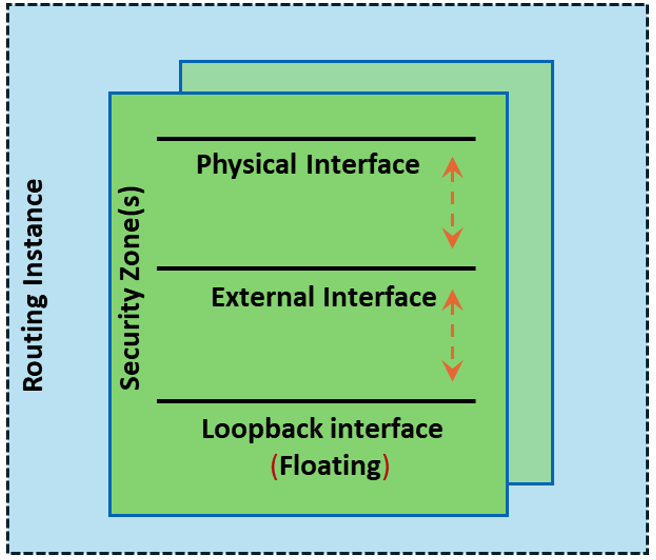
The primary point to convey relating to VPN with MNHA, is the relationship of the floating IP and consideration of routing instances. Previous sections covered the correlation with physical interfaces, security zones and routing instances. The same applies to the external interfaces used with VPNs.
When using multiple routing instances, understanding the relationships and dependencies for successful tunnel establishment is critical. Obviously, the physical interface is the point at which packets are sent and received between our tunnel endpoints. In non-MNHA deployments, the physical interface can also be the external interface. IKE negotiations occur with the external interface, as such, the VPN is essentially being terminated or anchored on the loopback interface.
With MNHA (synced tunnels), the external interface needs to have the capability to be serviced by either node in the cluster, dependent on which is active, a "floating IP address". The floating IP is assigned to a loopback interface, subsequently advertised towards the external network(s) to anchor the tunnel. In this scenario, there are two configuration requirements due to internal packet processing from a physical interface to a loopback interface.
- The loopback interface and the external physical interface used in the VPN configuration for the gateway must be configured in the same security zone. The below flow traceoptions exhibits the behavior if the loopback interface and the physical interface are in different security zones.
- An intra-zone security policy must allow for both IKE and ESP traffic to allow the IPSec tunnel to build.
How do we get IKE packets to and from the SRX to build the tunnel? The answer seems straightforward... but it's not just a reachability answer. The IKE gateway lookup process is centric with the external interface and its associated routing instance. Include MNHA and we need to consider that the external interface (the floating IP) MNHA is tracking, is also associated with a routing instance. These two routing instances need to be the same. MNHA's perspective routing instance is from where the Inter Chassis Link (ICL) is configured. Route leaking between two different instances isn't viable in the situation where the ICL and the floating IP-based loopback are in different routing instances.
The IKE gateway lookup is a control plane operation. While data plane flows can leverage route leaking to forward transit traffic across L3 boundaries, the IKE daemon initiates or responds to packets based on "local" routes (IPs configured directly on interfaces within that instance). It bypasses imported routes from other instances for this type of self-traffic decision. The floating IP and the ICL's management context need to be aligned within the same routing table to maintain session state and synchronization.
MNHA
Common acronyms and terms with basic definitions used in MNHA deployments below are for orientation.
- Inter Chassis Link (ICL), to synchronize state (RTO, Real Time Objects) for stateful failover, health/status check.
- Inter Chassis Datapath (ICD), to support asymmetric traffic flows.
- Service Redundancy Group (SRG) - is a logical grouping that can be selectively serviced based upon node priority.
- Activeness, concept of priority, which node is going to be the active node for a given SRG (higher priority is preferred).
- Signal Routes, routes installed (locally significant) based on node priority (activeness) to trigger conditional route advertisements.
- Conditional Route Advertisements, the basis for steering traffic to the active node, tightly coupled with signal routes.
An easy rule o f thumb for initial provisioning of an encrypted ICL is 1 Gbps per 100,000 concurrent sessions.
RTOs for session synchronization include session creation, session deletion, TCP state changes and additional request and response messaging. The minimum RTO message size is 320 bytes; with encapsulation and encryption overhead each RTO is approximately 400 bytes. A typical TCP session lifecycle generates 5-7 RTOS, accounting for session open, state changes, and close.
Factor in MNHA control heartbeats, IKEv2 keepalives, and potential retransmissions. New session establishment rate (connections per second) contributes burst overhead above the sustained concurrent session baseline - maintain ICL utilization below 75% to preserve headroom for post-failover resync and CPS bursts
-
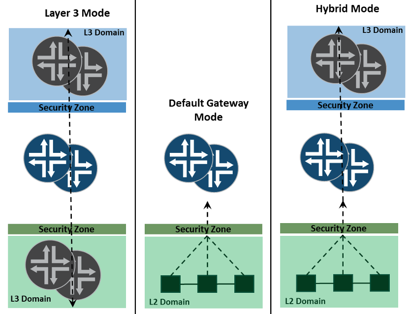
- MNHA Operational Modes
- Layer 3 (L3) Mode, provides stateful security for through traffic; no "directly" connected L2 resources or resources that use the SRX for a gateway. Conditional route advertisements are key.
- Default Gateway Mode - provides "directly" connected L2 resources via a VIP function like any First Hop Redundancy Protocol (e.g. VRRP).
- Hybrid Mode - combination of L3 and Default Gateway modes; when we want to associate (influence) traffic flows to the node that is actively for a VIP.
-
- Floating IP, An IP prefix on a loopback interface within a designated routing instance, used as the external interface for IKE gateway configurations and as the source for SRG activeness probes in L3 deployments. IKE gateway lookup, activeness probe resolution, and BGP conditional advertisement all resolve against the routing instance in which this prefix resides, mismatches will result in lookup failures.
I like to think of the floating IP as it's used with MNHA deployments more as an anycast IP versus a floating IP; the same (duplicate) IP address assigned to both nodes and advertised towards the network. Where a floating IP address is more of a single IP that shifts between nodes as in any first hop redundancy protocol (FHRP) or a virtual IP (VIP) typically leveraging some GARP-like mechanism to update L2 tables.
Though, unlike other anycast solutions, we use traffic steering methods and map activeness to a node to use for a specific function. Versus, either node can process ingress traffic and apply the function based on which node receives it (e.g anycast Rendezvous Point in Multicast/PIM networks).
Documentation references floating IPs - so we'll stick with that to avoid confusion.
Specific requirements when configuring IPSec with MNHA:
- Install new IKE package
- Must use SRG1+
- Identify IPSEC as a managed service
- Floating Address(es)
- Process packets on backup node (optional)
Installing the new IKE package with the following exec command you can validate the IKE process versus prior KMD process:
Beginning with the base MNHA configurations, identify local and remote peers, BFD detection, and encrypt the ICL with a VPN profile. Also, the routing instance and interface where the peering between the two nodes will occur for the ICL link.
Selecting the operational mode for your MNHA deployment is straightforward. Start with the question - What resources am I providing secure connectivity between? The VPN scenarios we're working with require connectivity with destinations protected by the SRX in the DMZ and INT zones. These destination resources use a VIP as their gateway. We want to keep symmetric flows (conditional route advertisements) between the VPN sources and the VIPs. The answer is hybrid-mode.
We can configure a single SRG to support both RA and S2S VPN connections, but we will be using two SRGs to further delve into potentials when supporting multiple SRGs; creating specific SRG based on VPN function/type (SRG1 for S2S and SRG2 for RA).
The next question then, is there a need for independent failover capability? Meaning if there were an event impacting either the RA-VPN connectivity or S2S VPN, do we trigger a holistic failover that shifts both groups of traffic over to the backup node as well or just the impacted group? Using multiple SRGs can create disparity between the active nodes, SRX-A active for SRG1 and SRX-B active for SRG2, or vice-versa, where traffic for a given session ingresses one node and egresses the other. Describing this cross-node forwarding pattern as a Z-mode (or Z-mode like) flow is distinct and entirely different from the Z-mode behavior in Chassis Cluster.
The testing in the following sections uses simple 5-tuple security policies without advanced inspection services (plugin inspections); under these conditions ICD will forward asymmetric packets and sessions will survive without impact. Where advanced inspection services are applied, sustained Z-mode flows from SRG activeness disparity are not a supported steady-state design, plugin inspection requires complete bidirectional flow visibility on a single node and session failures will result. During failover events ICD provides transient forwarding while routing converges; established long-lived sessions are typically tolerant of his window regardless of policy type. Traffic engineering should ensure complete flows traverse a single active node under steady-state conditions when advanced services are in policy.
We cannot have the same VIP configured in multiple SRGs. A simpler deployment using a single SRG to support both RA and S2S VPN is entirely valid; the two-SRG design here is used deliberately to explore independent failover capability and the behavioral differences between SRG configurations. SRG1 is configured in L3 mode for site-to-site VPNs. SRG2 is configured in hybrid mode, this describes how northbound ISP connectivity is handled, not where the RA tunnels terminate. In both cases, floating IPs on loopback interfaces anchor the tunnel endpoints; no VIP is used for tunnel termination. The distinction between L3 and hybrid mode determines how traffic is steered to the active node northbound, not where the tunnels terminate. MNHA accomplishes this steering through SRG-specific prefix lists and conditional route advertisements.
SRG-1 (L3 Mode) configuration
SRG-2 (Hybrid) configuration:
Asymmetric Flows with ICD
As of version 23.4R1, MNHA supports an ICD to additionally support asymmetric traffic flows. Not all packets associated with an asymmetric traffic flow are required to traverse the ICD. The ICD is engaged during initial TCP 3-Way handshake (Figure 8) and remains active until all content security plugins (advanced inspection services) have completed evaluation and detached from the session. Once plugins detach and no advanced services require continued full-flow visibility, the synchronized session can transition from warm to active on the receiving node, and subsequent packets are processed locally without ICD forwarding.
Examples presented walk through ingress flows, the same behavior is exhibited for egress flows.
The flows evaluated with either ICD or without ICD matched a traditional 5-tuple security policy without application ID or any other advanced security services applied:
When an ICD is configured, Application Tracking is one of those features where the SRX wants visibility for end-to-end flows.
ICD configuration:
Two basic asymmetrical flows are highlighted, neither of which use any NAT functionality. A ping test from a remote access VPN tunnel and an SSH connection. The ICMP test will demonstrate classic Z-mode connectivity, while the SSH connection is for connectivity not directly connected to the SRXs.
Ping, ICMP, isn't synchronized between the two nodes by default; most use cases don't require it. For testing purposes, we've enabled synchronization to more easily validate packets traversing the ICD.
With SRX-B active for the SRG, we explicitly configure the gateway on a target host (192.168.97.99) to SRX-A creating an asymmetrical (Z-Mode) flow. This same Z-Mode behavior is relative to other traffic flows, not just ICMP. ICMP was used to easily identify and track packets at relative points in the flow.
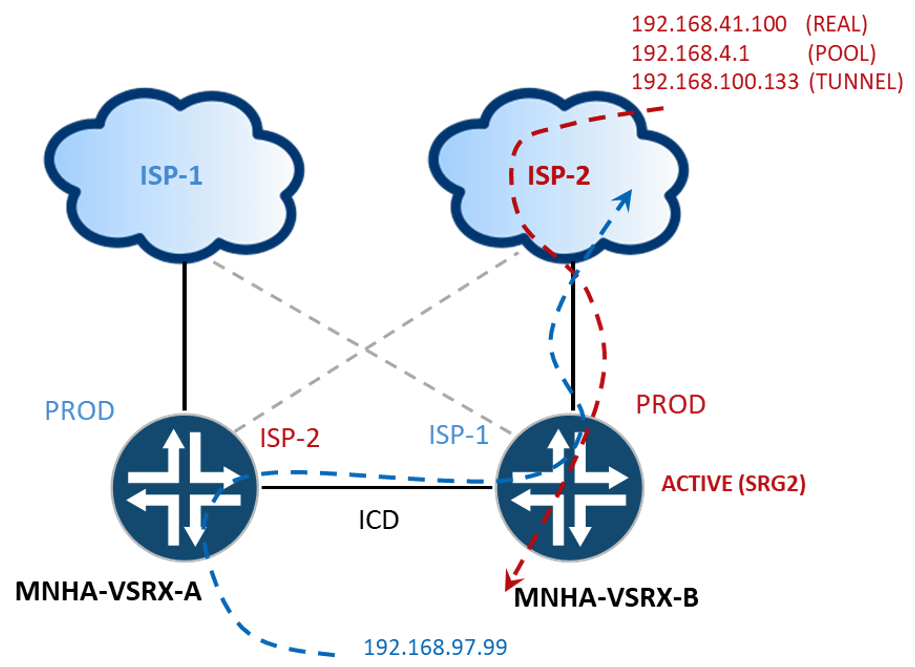
Initiating a 500-byte ping from source 192.168.41.100 across VPN tunnel (192.168.100.133 :: 203.0.113.100) to destination address of 192.168.97.99. An IP from the address pool, 192.168.4.1 was assigned to the client. Traffic was captured at the ingress interface (GE-0/0/2, physical interface bound to the VPN tunnel interface ST0.100) on the active node, MNHA-SRX-B, and at the ICD interface (GE-0/0/6) shown below.
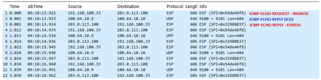
Notice the UDP encapsulation and additional 40 byte overhead.
The representative session tables identify the ingress traffic (ICMP Echo) at MNHA-VSRX-B on the tunnel and the return traffic (ICMP Echo Reply) on MNHA-VSRX-A. Wings show active, active on B, reachable via directly connected, with zero packets/bytes incrementing where we should see the return traffic incrementing by one. However, we see Warm/Active active on A. The warm flow is the synchronized Active flow for the ingress shown on MNHA-VSRX-B while the Active wing indicates incrementing packets/bytes processed on MNHA-VSRX-A.
Another example of asymmetry is with through traffic. Traffic that does not initiate or terminate with a source or destination that is "directly" connected to the SRX (providing gateway services). Figure 10 and subsequent flow information for an SSH connection originating from 192.168.100.133 to 10.177.177.77.
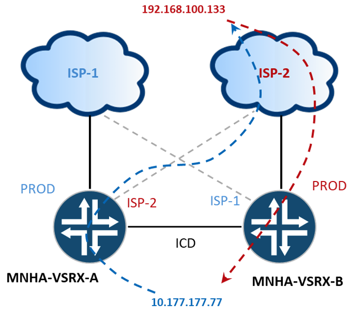
We can see the same Active/Warm sessions split between the B and A nodes as before. However, in this scenario, no session traffic is crossing the ICD.
In this environment, you can use the command, "show chassis high-availability data-plane statistics", to determine that packets are not using the ICD. This is a lot easier than implementing a packet capture.
With increasing traffic counters for sent and received packets for the synchronized flow (show security flow session), there is no incrementation of either sent or received packets in the data-plane statistics for ICD Data.
Let's take a deeper dive into this flow. The previous conversation was from a look at an active session, past the initial setup. During initial setup, the SYN will pass through SRX-B, the asymmetric SYN-ACK will ingress into SRX-A, cross the ICD, and egress SRX-B. Completing the 3-way handshake, the path of the final ACK is identical to the initial SYN (Figure 11). Once complete, the remainder of the asymmetric flow will not traverse the ICD and egress via SRX-B (Figure 10).
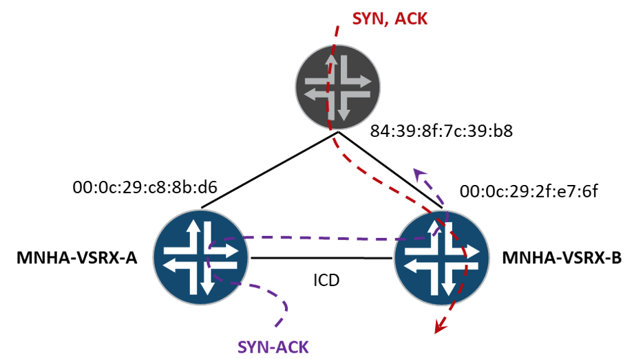
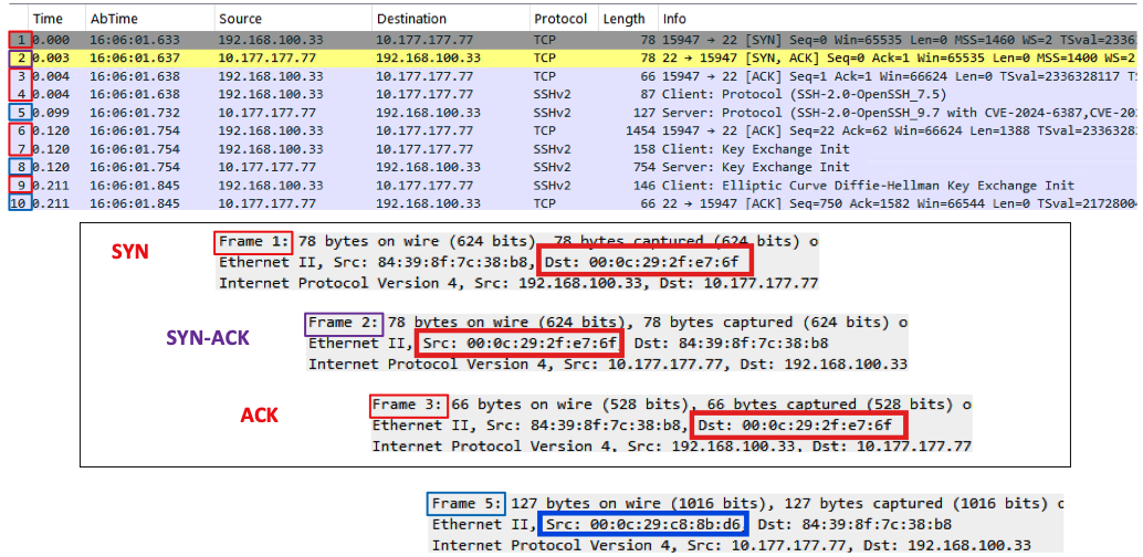
Validating the source and destination hardware addresses in the packet capture below, we can see that 00:0C:29:2F:E7:6F (SRX-B) sends and receives the three-way handshake packets, while frame 5 shows an egress packet via SRX-A (00:0C:29:CB:8B:D6).
Just a little deeper and we'll round out this discussion about the ICD. What happens if we have this established asymmetric flow, no other changes to either North or South bound routing, and the link between SRX-A and ISP-2 fails (the active return path)? Will the flow drop? No. The SSH traffic will shift across the ICD. Similarly, when the failed link returns to service, the original flow characteristics will resume without traversing the ICD.
However, if the ICD is down, our SSH session fails.
From 192.168.100.33, "ssh: connect to host 10.177.177.77 port 22: Operation timed out"

Respective flow information on SRX-B and SRX-A is correct but 192.168.100.33 is not getting a SYN-ACK returned.
The SRX isn't forwarding the SYN-ACK at all. Further research indicates that SRX-A is attempting to forward the SYN-ACK across the down ICD link.
Similar to the ICD down scenario above, ICL latency can produce the same type of drop. If the latency between the nodes supporting the ICL connectivity is such that the RTO isn't processed on the peer node and return traffic arrives on the backup node (before session sync), that traffic will be dropped. If designing to support asymmetrical flows, factor the ICL latency accordingly.
Proxy ARP with ICD
With MNHA, NAT configurations should be identical between the two nodes to support stateful fail-overs. With NAT, if we're doing a translation for an address that the firewall doesn't "own" (configured locally on an interface) and is within the same subnet (broadcast domain), we typically use proxy ARP. This is not an issue with interface NAT as the IP and HW addresses will be unique between the nodes' interfaces.
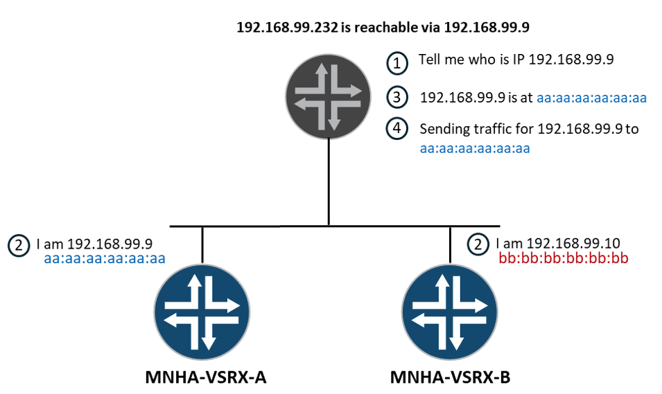
Proxy ARP will only reply to ARP requests, not initiate an ARP request. The SRX will source the IP assigned to the interface for any ARP resolutions. Figure 14 frames the picture of an upstream device 'ARPing' for the hardware address of an IP 192.168.99.232. The SRXs have SNAT and proxy ARP configurations to answer for 192.168.99.232. Both SRXs will reply to the request. The upstream device can only have 1 ARP entry to IP address in its table, usually the first received reply is honored. If SRX-A forwards a SNAT packet to the upstream device, all is well, until the upstream device returns the packet back to SRX-B with an ICD configured.
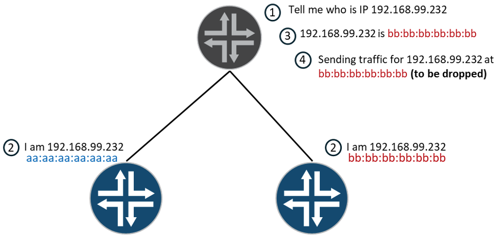
Each MNHA node maintains an independent control plane, which means both nodes will respond to proxy-ARP requests. Deployments that rely on proxy-ARP for upstream reachability to the virtual IP, such as those migrating from Chassis Clustering, will need to transition to a L3 routing solution where the upstream device routes directly to the VIP. Without this, a node receiving a packet for a session where NAT was performed on the other node will drop it, show security packet-drop records will report "Dropped by FLOW:error info in MNHA flow meta header". This message can be a useful indicator when troubleshooting asymmetric drop scenarios during migration.
Without the ICD configured, the MNHA pair will process traffic similarly as described in the next section.
Asymmetric Flows without ICD
Let's look at the same two session examples (no NAT function) used in the previous ICD section for comparison: the 500-byte ping Z-Mode test via the RA-VPN tunnel and the SSH asymmetric connection. Regarding the ICMP test, without an ICD configured, the return path is different. Instead of returning to the origination via ISP-2, the encrypted packet is forwarded towards ISP-1.
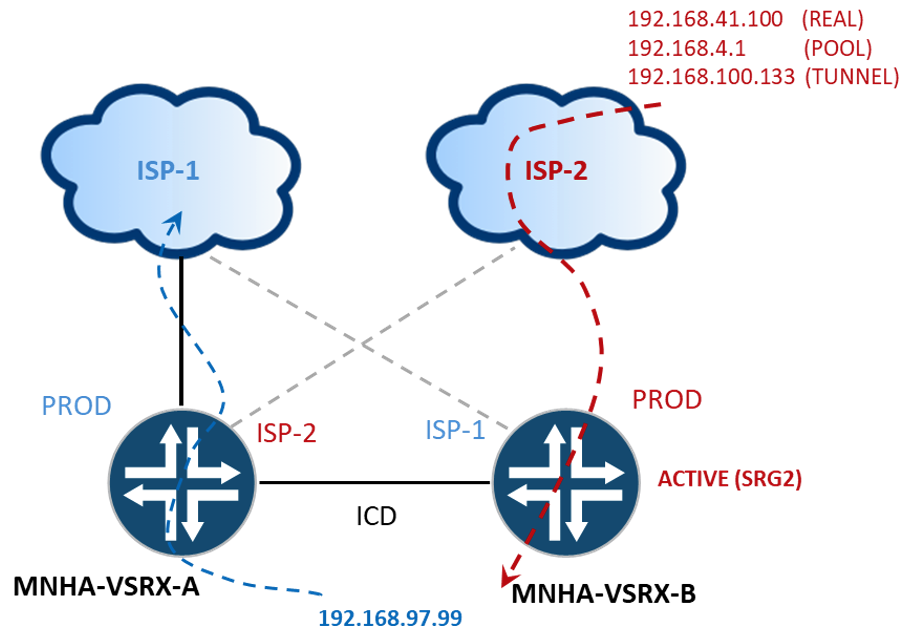
Three merged packet captures show this behavior with better detail. Frame 56 is our encrypted ingress ICMP ECHO-REQUEST processed at SRX-B (destination MAC address for GE-0/0/2). Frames 57 and 58 show the host receiving and replying to the ping. Frame 59 is the egress encrypted ICMP ECHO-REPLY sent from SRX-A (source MAC address for GE-0/0/1) toward ISP-1.
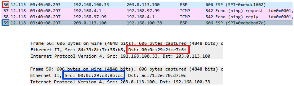
The SSH test performed the same with or without an ICD configured.
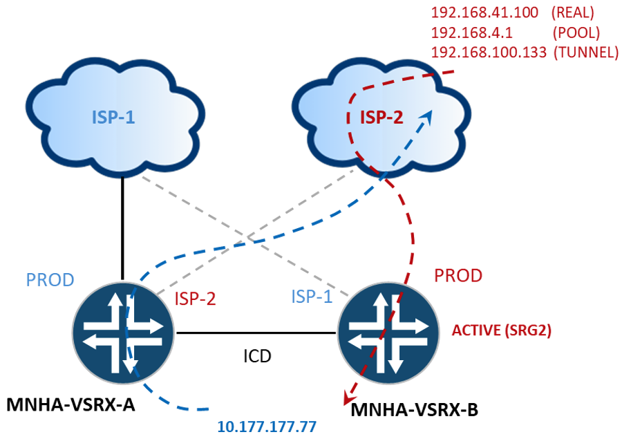
Again, we'll validate the ingress and egress interfaces by looking at the hardware addresses of the interfaces: Frame 1 = SRX-B, Frame 2 = SRX-A, Frame 3 = SRX-B.
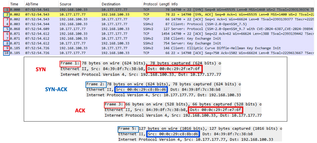
Notice the "From Zone" in the output shows EXT-2 while the ingress interface aligns with GE-0/0/2.0 where the return packets are forwarded.
Session creation for the flow (active wing), on SRX-B, installed the forwarding direction, interface ge-0/0/2.0. Now what if that link goes down? Does the traffic fail? Yes.
Another critical point to factor into designing MNHA deployments. The scheme used for interface connectivity needs to be identical to support any asymmetric flows.
NAT Considerations
During flow processing, there is a route-lookup function to determine the security zone, subsequent interface and next-hop to forward traffic to. Before a session is created, the route-lookup function does more than just determine egress interface and zone. Reverse Path Forwarding (RPF) check as well as Reverse Route Lookups (RRL) are performed before certain NAT operations. RPF checks if the source IP is reachable via the same interface the packet arrived on, if the interface is different the packet is dropped (think IP Spoofing mitigation). The Reverse Route Lookup is a mechanism that ensures the return traffic for a session is sent back through the correct, symmetric path (think Zone-to-Zone consistency).
Source NAT (SNAT)
Regarding a single route table that has two route entries (default route) reachable via different destinations A or B, the forwarding decision will select one of the two next-hops, A or B. Now if we want to NAT that traffic, as with typical ISP connections, we need to consider the impacts of RPF and RRL.
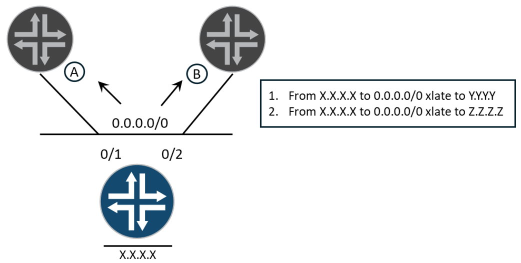
Source NAT (SNAT) functions occur after the L3 lookup. NAT configurations are processed linearly, from top to bottom (reading a list). If we first define an entry that translates an address (interface or range) that matches the forwarding path (A::A) then there shouldn't' be any issues with our egress traffic (matching forwarding path with SNAT configuration). If the next lookup selects the also valid path with the next-hop towards B, the SRX will perform the NAT operation, and the upstream device will drop the packet. This B:A pattern is problematic.
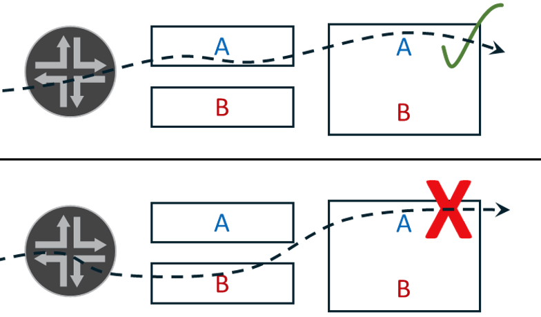
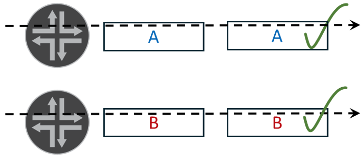
A solution is to configure discrete routing instances, separating the tables and relative A/B interfaces (ISP-1/ISP-2) and mapping discrete lists for NAT processing. This results in a predictive L3 lookup and source NAT translation (Figure 21).
Another approach worth considering is with the source NAT rule-set to interface construct, 'set security nat source rule-set X to interface'; binding a rule-set to a specific egress interface with a corresponding SNAT pool. Unique SNAT pools advertised exclusively to their respective ISPs, the return path is deterministic and 'to interface' can work effectively. However, consider:
- If a common or shared pool range is used, the same prefix is reachable via both ISPs and return traffic becomes non-deterministic and can cause end-to-end flows to fail.
- Splitting the pool range, or using unique ranges, per ISP resolves the return path, but introduces additional operational dependencies regarding ECMP hash consistency, correct per-ISP prefix advertisements, and disciplined SNAT rule-set to pool mapping are dependencies that all need to align. A misalignment can cause traffic failures and increase the difficulty in diagnosing these types of faults.
The examples used and discussed in this post use a shared pool and separate routing instances. Again, mileage varies....
The bow-tie journey begins...
SNAT Pools without Proxy ARP
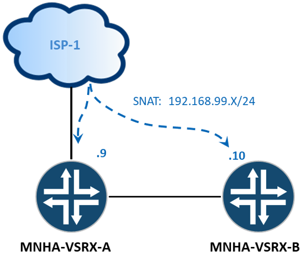
Continuing with the above SNAT pool example for 192.168.99.232 we can explicitly tell the upstream router to send return traffic to the IP address assigned to the physical interface (GE-0/0/1) of the SRX that initiated the flow. The upstream router would then only need an ARP entry for the physical interface of the SRX and not for 192.168.99.232.
What about redundancy? We can solve the problem with routing, such that we weight the routes in so return traffic always prefers A, unless A is down, then use B as the next-hop.
Note: In Junos 25.4R, the limit of 32 VIPs per SRG is raised to 2,000.
This may be an issue if your ISP will only accept certain prefix lengths or provides a single static route back. Also, there is an increased potential for asymmetrical traffic patterns. Instead of pointing the next-hop to the SRX interfaces, you can point them to a VIP.
Adding an additional 2 VIPS, 1 for the ISP-1 (192.168.99.129) and 1 for ISP-2 (192.168.98.129):
Different SNATs, Different ISPs
In cases where there will be different SNAT pools per ISP and a failover event occurs, requiring traffic to be SNAT'd into a different address range, expect active connections to fail and require reestablishing. If you have a common prefix that you can announce to both ISPs, then stateful failover is possible. The common prefix we'll use in our examples will be 203.0.113.0/24.
BGP and Routing Policies
Border Gateway Protocol (BGP), tomes have been dedicated to this subject. BGP is not the only protocol you can use to influence traffic flows, but it is popular, highly configurable, and versatile for traffic engineering especially with MNHA designs. The examples illustrate a few methods to control traffic in and out of the MNHA pair:
- AS Path Prepends, to influence ingress traffic by creating a less desirable path (shorter paths preferred) across Autonomous Systems (AS).
- Multi Exit Discriminator (MED), influence ingress traffic from adjacent AS with multiple exit points (lower metric preferred).
- Local Preference, influence egress traffic within the AS (higher preferred).
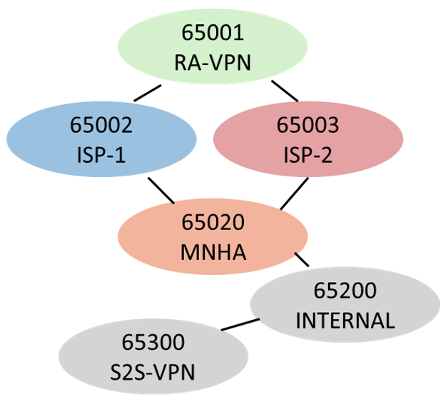
In the example below, we'll just be ingesting the default route via BGP from each of the ISPs. The SRXs (AS65020) are "directly" connected to the ISPs (AS65002 and AS65003), similarly the SRXs can be connected to an intermediary L3 pair of edge routers and then to the ISPs. AS65001 will be where the remote access VPN clients originate from while AS65300 will source S2S VPN connections.
With symmetry in mind, we want ingress and egress traffic to follow the same path regarding the active MNHA node for the SRG.
Dual uplinks to different provides, multiple routing instances, MNHA, NAT scenarios and considerations for terminating VPN tunnels can be a challenge. Similarly, how we scratched the surface on how MNHA deployments support asymmetric flows with or without an ICD, we cover a few scenarios which underscore additional reasons to encourage symmetric traffic flows. The scenarios that we'll investigate are:
- 1) Gateway Lookup Failure (ISP Routing Policies)
- 2) IP Spoofing (ISP Routing Policies)
- 3) Non-MNHA Asymmetrical Flows (Internal/External)
ISP Routing Policies
| Node/Status | ISP-1 (RI:PROD/SZ:EXT) | ISP-2 (RI:ISP-2/SZ:EXT-2) |
|---|---|---|
| SRX-A (SRG-2) | MNHA_ROUTE_POLICY_ISP | MNHA_ROUTE_POLICY_ISP_BACKUP |
| Active | Best Path | Backup Path |
| Backup | Backup Path | Backup Path |
| Node/Status | ISP-2 (RI:PROD/SZ:EXT) | ISP-1 (RI:ISP-1/SZ:EXT-1) |
|---|---|---|
| SRX-B (SRG-2) | MNHA_ROUTE_POLICY_ISP_BACKUP | MNHA_ROUTE_POLICY_ISP |
| Active | Backup Path | Best Path |
| Backup | Backup Path | Backup Path |
Table 1. ISP route preferences
Starting with a high-level intent of how we want to influence traffic to and from our ISP connections. A single prefix 203.0.113.0/24 will be advertised northbound to both ISP-1 and ISP-2 to cover our SNAT pools. From that same /24, we'll advertise the /32 for the floating loopback for tunnel anchoring. A single prefix for the default route is received from the ISPs.
Signal routes for SRG-2 that will be the trigger or matching condition for the route treatment will be 169.254.200.3 and 169.254.200.4. If one of the SRXs sees 169.254.200.3 in its routing table, the role is active. Vice versa, if an SRX sees 169.254.200.4, the role will be that of backup. The SRX will only see one of these signal routes, not both. Creatively, we'll name the route policies MNHA_ROUTE_ISP and MNHA_ROUTE_POLICY_ISP_BACKUP (Table 1).
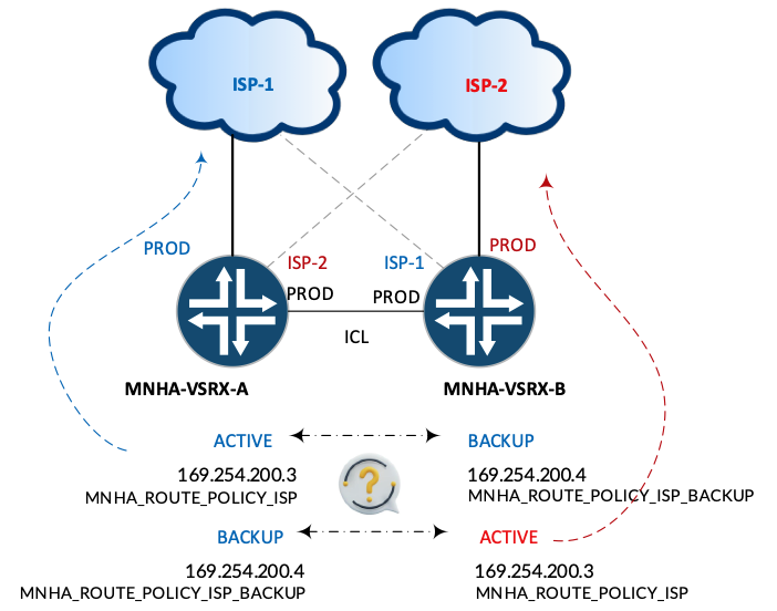
When configuring the active/backup signal routes if you don't specify the routing instance, the SRX will modify inet0. Wherever the signal routes are added, based on active/backup role status, we'll need to match for investigating the existence of the signal route.
Gateway Lookup Failures, Ingress Control (AS Path Prepend)
Avoid the dreaded "Gateway lookup failed" situation. If VPN tunnel initiation traffic is received at an external interface that is in a different routing-instance (RI:ISP-1 or RI:ISP-2) than the floating IP (RI:PROD), an IKE GW-LOOKUP-FAILURE event is created (Figure 27) resulting in a failed IKE Security Association (SA).
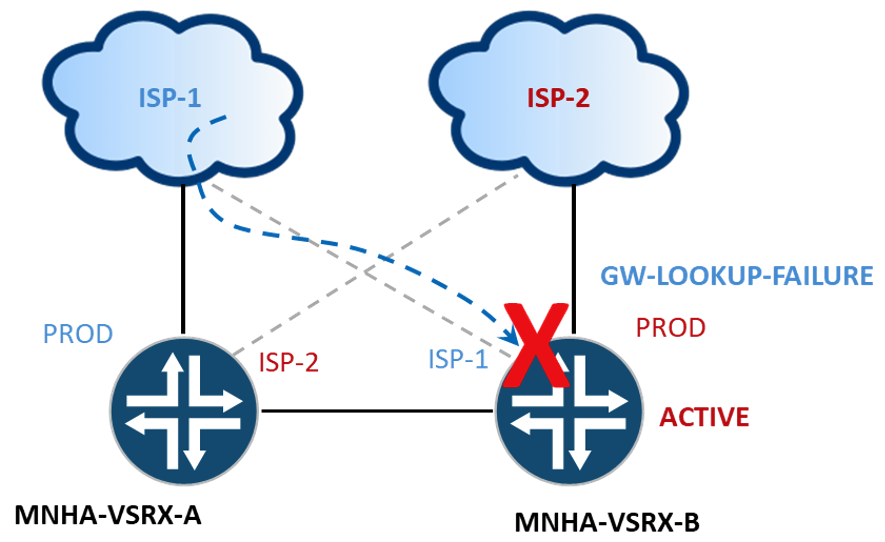
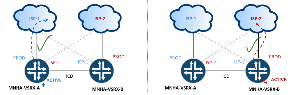
This is an example for ingress control, advertising the 203.0.113.100/32 prefix ensuring that the preferred path is via ISP1 to the PROD instance on SRX-A and if SRX-B is active then we want the preferred path to be that from ISP-2.
Another bow-tie moment... If we didn't advertise any prefixes Northbound (SRX-A to ISP-2 or SRX-B to ISP-1) there isn't any potential for the ISP routers to forward traffic to the non-MNHA routing instance.
We only conditionally advertise the floating-ip our RA-VPN clients connect to. The shared SNAT prefix does not need to be pinned to a single node. Notice in the MNHA_ROUTE_POLICY_ISP below, the prepended advertisement if the backup signal route is present. Not required for functionality.
MNHA_ROUTE_POLICY_ISP (A side):
MNHA_ROUTE_POLICY_ISP (B side):
Traditionally, the BGP multihop feature is used to support eBGP peering between IP addresses that are not on the same local subnet, often between loopback interfaces. To modify the next-hop to an address on the same subnet, not the self IP used for the peering, we will need to use multihop. Without multihop, the next-hop for the advertised prefix will be the self IP used in the peering.
Without multihop:
With multihop:
Alternatively, the ISP routers would need a configured route for the advertised prefix to the VIP.
IP Spoofing, Egress Control (Local Preference)
Another potential issue is with return traffic. With default configurations, IP Spoofing (RPF) will drop traffic if the path back to the originator is different (Figure 28).
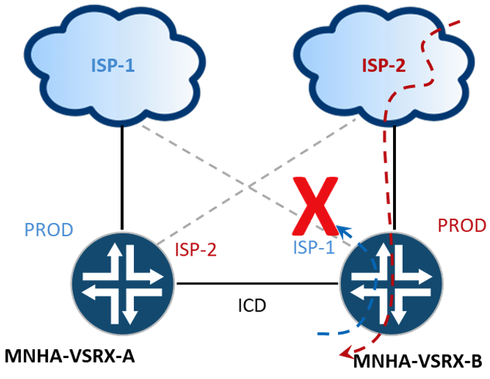
For this example, we'll influence the egress direction by changing the local preference of the default route received from the non-PROD routing instance. Yes, if we didn't receive these default routes we wouldn't need to update (bow-tie...).
The SRXs have both default routes in the table. The preferred selection is the default with the local preference of 100 (default) over 50.
Non-MNHA Asymmetrical Flows, Ingress Control (Local Pref plus)
Flows that ingress the MNHA cluster via a routing-instance that isn't associated with MNHA (RI:PROD), that are asymmetrical, are subject to traditional processing and enforcements as if the flow was traversing two independent SRXs. The ICL in our discussions is in the PROD. Figure 29 shows traffic received on an interface in the ISP-1 RI - Routing Instance mismatch per say. There will not be any flow synchronization between the two SRXs.
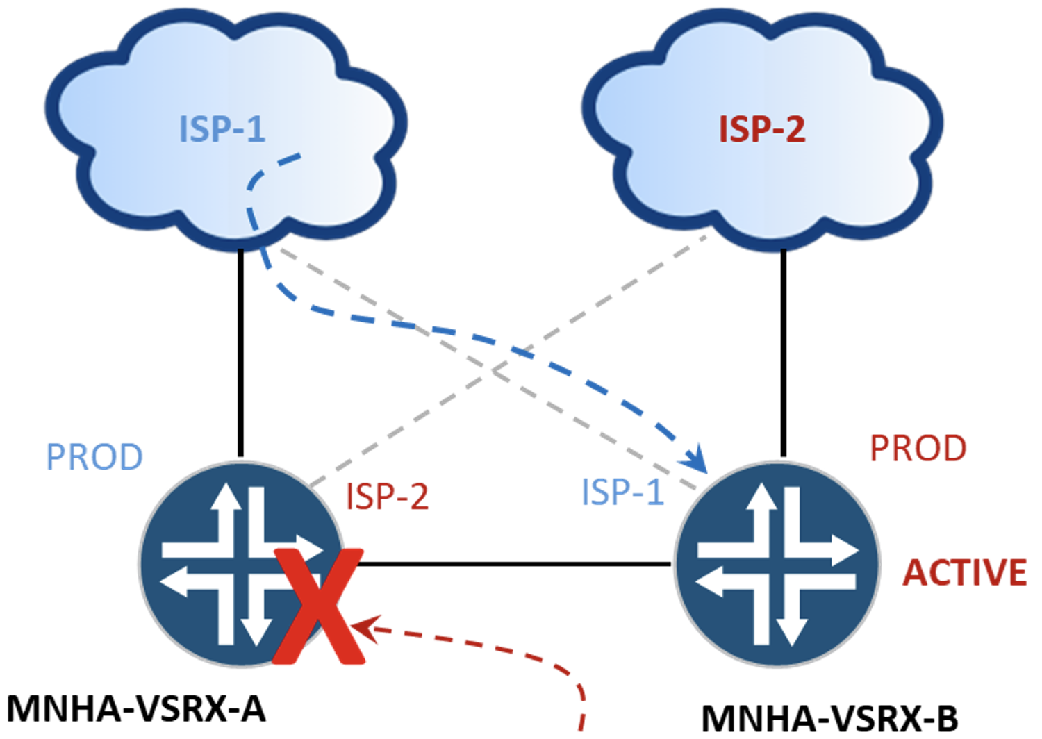
SRX-A sees the SYN-ACK without first seeing the SYN and will drop the packet accordingly - TCP SYN Checking. The concepts of MNHA are not applicable to ingress flows from a Routing Instance that is not where the ICL is configured.
The complete solution is a combination of the ingress routing policies at both sides of the connection, ISP and Internal.
Internal Routing Policies
The Internal/Extranet example topology is purposefully different from the ISP examples (Figure 30). The ISP examples had a single peer point to different adjacent AS from each of the SRXs. Here, the SRXs will have a single peering each into the same adjacent AS. There isn't a potential RI mismatch, so we can advertise the default route without any treatment if we want downstream ECMP capabilities. We want to influence the following prefixes:
- 10.165.251.200/32 is the floating IP used with site-to-site tunnel.
- 192.168.97.0/24 and 192.168.252.0/24 are DMZ/INT subnets supported by our VIPs.
- The 192.168.251.x/25 prefixes are to support troubleshooting efforts with tools like traceroute.
Beginning with the high-level intent of how we want to influence traffic towards our "internal" network (Table 2).
| Node/Status | RTR-A (RI:PROD/SZ:EXT) |
|---|---|
| SRX-A (SRG-1) | MNHA_ROUTE_POLICY |
| Active | Best Path |
| Backup | Backup Path |
| Node/Status | RTR-B (RI:PROD/SZ:EXT) |
|---|---|
| SRX-B (SRG-1) | MNHA_ROUTE_POLICY |
| Active | Best Path |
| Backup | Backup Path |
Signal routes for SRG-1 that will be 169.254.200.1 and 169.254.200.2.
Prefix lists configuration:
Routing policy configuration:
While the MED will influence a decision towards our MNHA cluster as AS65200 has 2 exit points toward AS65020, additional configuration on the routers is needed due to the iBGP link between them. Production deployments should consider additional policy terms to account for transitional node states such as boot or ineligible; ensuring path selection remains deterministic regardless of SRG condition.
IPSEC VPNs
Internet Protocol Security (IPSec) can be used to securely tunnel encrypted traffic across less trusted (or not at all) networks. Two types we'll look are for remote access (aka user) and site to site. Before we dig into the configurations let's look at some common observations relative to IPSec tunnels and MNHA.
With MNHA IKE/IPSEC, Security Associations (SAs) status can be viewed on either node, further narrowed down by SRG. Below is shown IKE Security associations from both SRX-A and SRX-B.
While the information presented is the same, the tunnel is established to the active node for the SRG.
Additional validation of where the tunnels anchored can be evaluated in the session tables by looking at the HA State (Active or Backup). For a more focused view use "show security flow session tunnel".
Both nodes have identical tunnel configurations. To view traffic a specific node is forwarding on its tunnel interface, use the show interface st0.x command. Traffic statistics are specific to the node and not sync'd between the two. The following shows a symmetric traffic pattern as we increment both transmit and receive on a single node's tunnel interface.
Asymmetric patterns will show input packets (or output packets) on one node while output (or input) packets on the other node incrementing for the session.
Remote Access VPN
Observations:
- IKEV1 aggressive mode sessions aren't synchronized across. IKEv1 requires the VPN client to re-authenticate and re-establish the tunnel with the new active node upon failover.
- When adding certs, you only need to add the cert on 1 node. The certificate will be synchronized to the 2nd node as long as the ICL is up and in sync - "Cold Sync Status: COMPLETE"
We will explore a full tunnel example (no split tunnelling). All traffic from the client is sent to the SRX for inspection and forwarding.
Addresses will be assigned from pools based on group information provided from RADIUS server (Framed-Pool attribute) from 192.168.4-6.0/24. In an active-active scenario with multiple SRGs, then a different address pool (or split the /24s in half and assign 1 half to node A and the other to node B per SRG) is required. It is not necessary to do with a single SRG as in our setup.
Consider a tunnel active on SRX-A. The client is assigned an address of 192.168.4.4 from the pool.
If a failover event is triggered, the assigned IP for the client from the pool moves to SRX-B.
If while SRX-B is active, new connections will pull from the same pool. Similarly, if we failback, all the addresses used from the pool will follow, without collision. If a different range was used for the same SRG pool, then when failing back and forth the tunnel connections would drop as the pool is not common. With multiple SRGs, there is a possibility of address collisions, hence the requirement for separate (shared) ranges between the nodes.
Address pool configuration
IKE Proposal configuration:
IKE Policy configuration:
The external interface is the interface that is associated with the configuration the floating IP address (lo0.10). The local address, 203.0.113.100/32, is monitored with MNHA (prefix-list). 203.0.113.100 resolves to mnha-ra.winlab.local and is what the client will initiate its connection to.
IKE GW configuration:
IPSec proposal configuration:
IPSec policy configuration:
IPSec VPN configuration:
In Junos OS Release 23.1R1 and later, the default-profile option is deprecated. The new profile names use FQDNs or IPs to identify the remote connections.
The profile entry matches that of what the client uses to connect with.
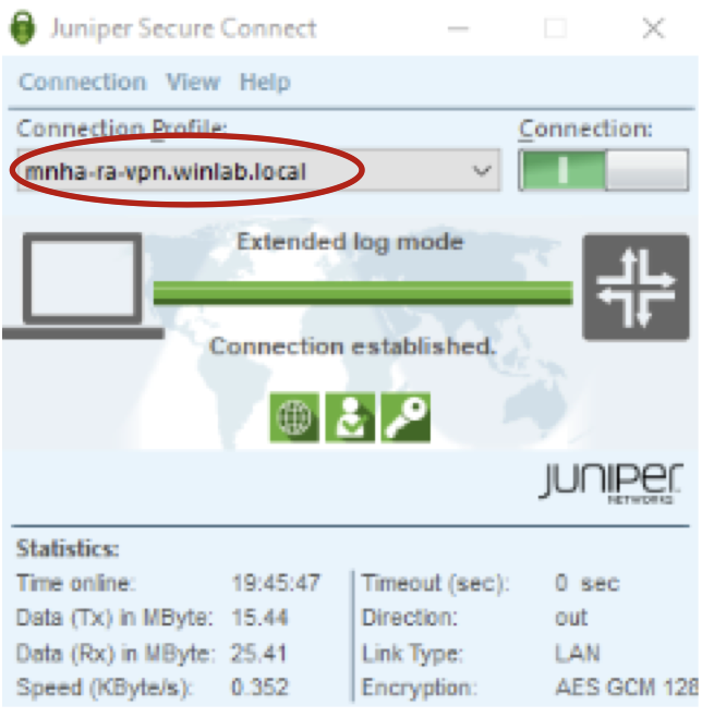
In MNHA, the control planes are independent. RADIUS configurations are specific to the node as well as connectivity from each node to the RADIUS server.
Additional configurations:
Site-to-Site VPN
The site-to-site VPN example is very basic. The only added twist is that the tunnel interface is in a different routing-instance. Reference for IPSec configurations: Active/Active, Dynamic Routing Protocols, and ADVPN.
IKE Proposal configuration:
IKE Policy configuration:
Again, the external interface is that of lo0.10 but the local address is 10.165.251.100, floating IP in SRG-1.
IKE GW configuration:
IPSec proposal configuration:
IPSec policy configuration:
IPSec VPN configuration:
When the tunnel builds, Auto Route Insertion (ARI) will add the prefix for our traffic selector in the PROD RI, for 192.168.249.0/24, on both MNHA nodes.
The tunnel interface st0.200 resides in the VPN RI. We're not beholden to the same restriction regarding the IKE-GW. There needs to be routing to and from the PROD RI and VPN RI for successful connectivity.
Keeping it Simple
If you've made it this far without skipping ahead, you might think that MNHA is overly complex. The purpose of including the bow-tie design with dual ISPs was to enforce concepts and principles related to MNHA and how MNHA may be incorporated into network architectures. Mileage varies...
Initial questions to answer before you begin your MNHA journey:
Asymmetrical Flow Support?
- Advanced Security Services = ICD
VPNs?
- Need IKED
- Encrypt ICL
- SRG (other than SRG0)
Multiple Routing Instances?
- ICL, Floating IP (Loopback) and Physical Interface in same RI
NAT/SNAT?
- Use L3 over Proxy ARP
If the goal is to load-balance traffic through the MNHA pair, instead of making an ECMP decision on the firewalls, move that functionality outside of the firewalls. This type of ECMP flow-based load-balancing can be viewed with the screen capture from Security Director Cloud (SDC) below.
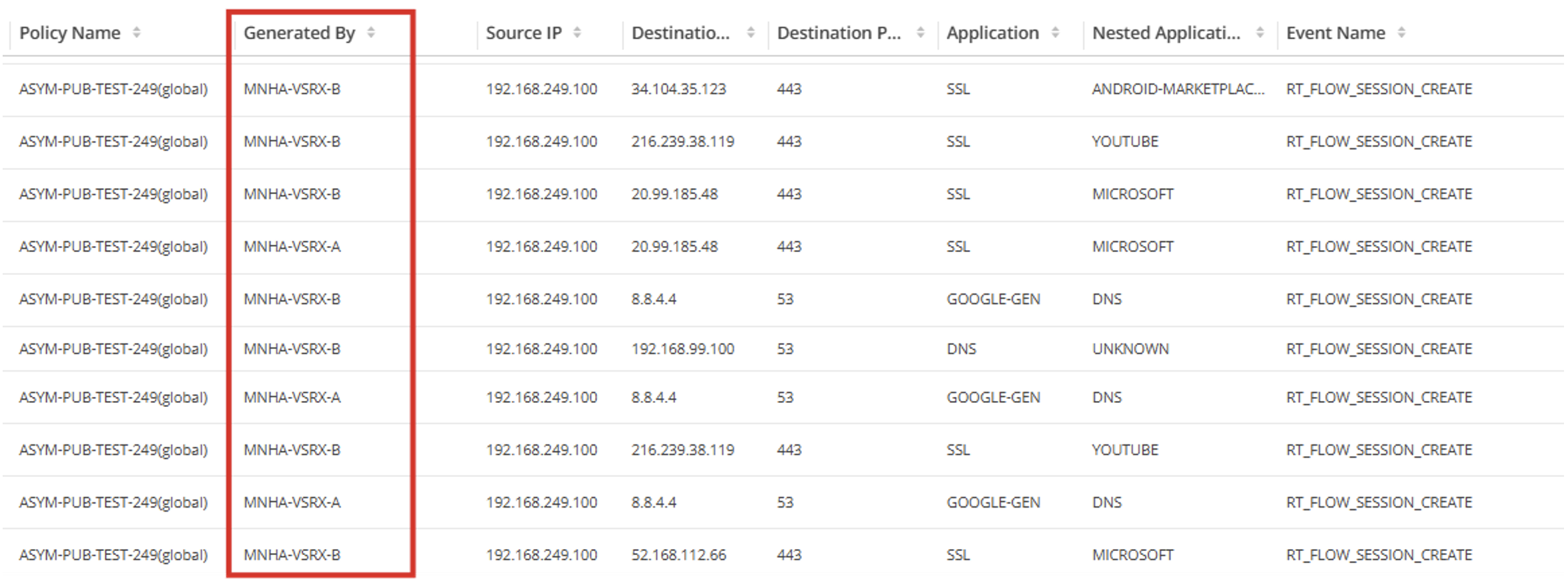
Reduce complexity. Simplify the number of routing tables, e.g. use a single one. Keep in mind any asymmetric potentials, scope the ICL and ICDs for appropriate BW usage.
Appendix A: IP Connectivity Diagram
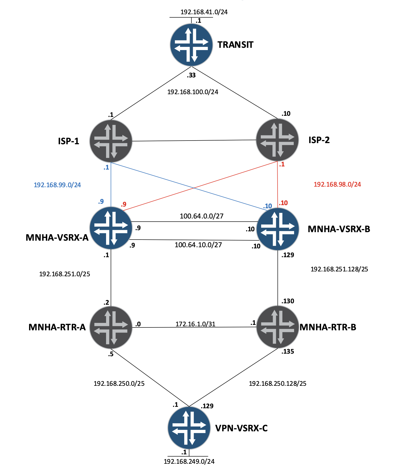
Appendix B, MNHA INT/SZ/RI
Appendix C - Full Configurations
Link to full configurations: https://github.com/JNPRAutomate/mnha-ipsec-and-multiple-routing-instances
Summary
A colleague once told me, "If you're a network (router) guy you will have designs with multiple VRFs. If you're a security (firewall) guy, you'll just have one, inet0." Just because you can doesn't mean you should.... It's imperative to understand the requirements to design and implement a successful, supportable solution.
Don't add complexity for the sake of it. Reference organizational security policies and standards. Understand traffic flows, expectations and functionality, not only for efficient operations but for more efficient support and troubleshooting.
Useful links
- Multi-Node High Availability: public documentation https://www.juniper.net/documentation/us/en/software/junos/high-availability/topics/topic-map/mnha-introduction.html
- Multi-Node High Availability Basics https://juniper.github.io/techposts/multi-node-high-availability-basics/article
- Hybrid MNHA with eBGP https://juniper.github.io/techposts/hybrid-mnha-with-ebgp/article
- SRX clustering: from Chassis Cluster to MultiNode High Availability https://juniper.github.io/techposts/srx-from-chassis-cluster-to-mnha/article
- Flow-Based and Packet-Based Processing User Guide for Security Devices https://www.juniper.net/documentation/us/en/software/junos/flow-packet-processing/topics/topic-map/security-srx-devices-processing-overview.html
- Chassis Cluster Fabric Interfaces https://www.juniper.net/documentation/us/en/software/junos/chassis-cluster-security-devices/topics/topic-map/security-chassis-cluster-data-plane-interfaces.html
- IPSec VPN Configuration Overview https://www.juniper.net/documentation/us/en/software/junos/vpn-ipsec/topics/topic-map/security-ipsec-vpn-configuration-overview.html
- Public Key Infrastructure Guide https://www.juniper.net/documentation/us/en/software/junos/pki/topics/topic-map/enroll-certificates.html
- Juniper Secure Connect User Guide https://www.juniper.net/documentation/us/en/software/secure-connect/secure-connect-user-guide/topics/concept/juniper-secure-connect-for-windows.html
- [SRX] Traffic loss when IPsec VPN is terminated on loopback interface https://supportportal.juniper.net/s/article/SRX-Traffic-loss-when-IPsec-VPN-is-terminated-on-loopback-interface
- [SRX] How to troubleshoot a VPN that is up, but is not passing traffic https://supportportal.juniper.net/s/article/SRX-How-to-troubleshoot-a-VPN-that-is-up-but-is-not-passing-traffic
- Issues with Juniper Secure Connect Configuration with rsa-signature proposals https://supportportal.juniper.net/s/article/Issues-with-Juniper-Secure-Connect-Configuration-with-rsa-signatures-proposals
- [SRX] VPN does not fail back to primary gateway https://supportportal.juniper.net/s/article/SRX-VPN-does-not-fail-back-to-primary-gateway
- [SRX] How to perform ISP failover on dual ISP scenario where ISPs push default route over DHCP... https://supportportal.juniper.net/s/article/SRX-How-to-perform-ISP-failover-on-dual-ISP-scenario-where-ISPs-push-default-route-over-DHCP-access-internal-route-and-the-ISPs-use-dynamic-IP-addresses-as-well
- Github with all config files: https://github.com/JNPRAutomate/mnha-ipsec-and-multiple-routing-instances
Glossary
- ARI - Auto Route Insertion
- AS, Autonomous System
- BFD, Bi-Directional Forwarding Detection
- BGP, Border Gateway Protocol
- ECMP, Equal Cost MultiPath
- HA, High Availability
- ICD, Inter Chassis Datapath Link
- ICL, Inter-Chassis Link
- L2, Layer 2
- L3, Layer 3
- MED, Multi-Exit Discriminator
- MNHA, MultiNode High Availability
- RI, Routing Instance
- RPF, Reverse Path Forwarding
- RRL, Reverse Route Lookup
- SDC, Security Director Cloud
- SRG, Services Redundancy Group
- VIP, Virtual IP
- VRF, Virtual Route Forwarding
Acknowledgements
The collective team that reviewed and provided valuable feedback, namely Karel Hendrych and Scott Astor. Plus... Nicolas Fevrier for overseeing the Tech Posts site and handling all the publishing tasks.