This TechPost will cover configurations, monitoring, and test plans for provisioning 400G OpenZR+ Optics. In designing a Dark Fiber Network, it is important to do link budget calculations. Network operators typically require margins in anticipation of additional splices due to fiber breaks and insertion of repair cables. Do we really need this margin? Let's figure out from the tests shown in this article.
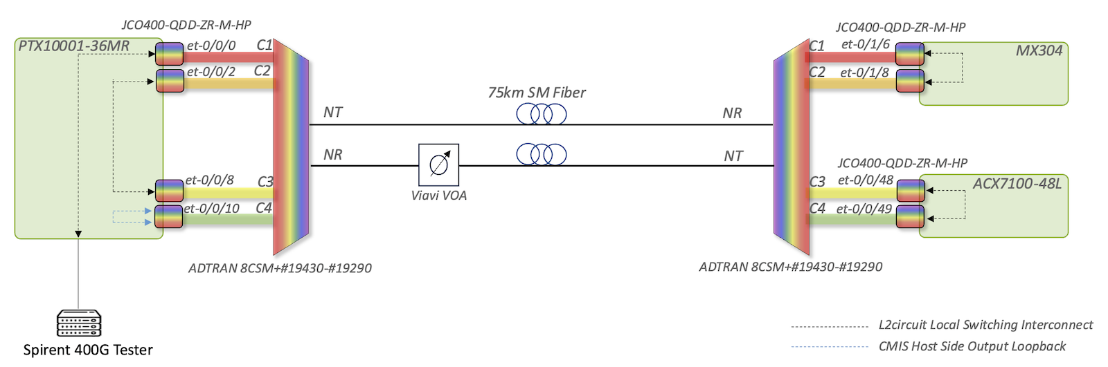
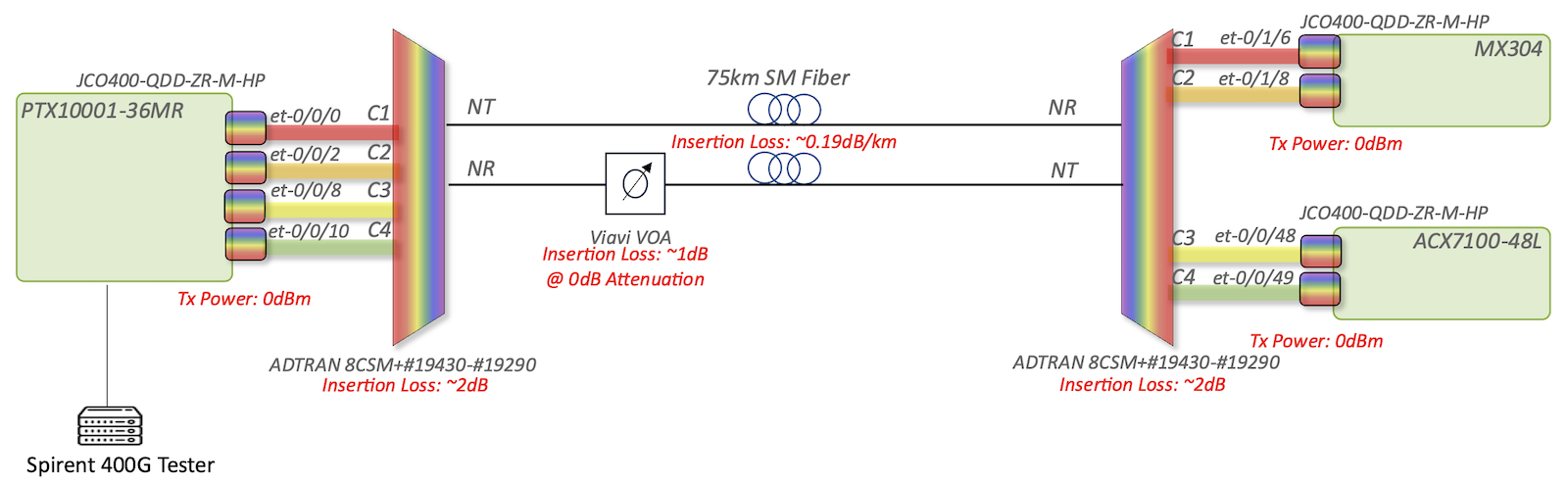
The topology will use JCO400-QDD-ZR-M-HP as transceivers; PTX10001-36MR, ACX7100-48L, and MX304 as routers; and ADTRAN 8CSM+#19430-#19290 as Mux/DeMux. A 75 km fiber optic cable will be used and a Variable Optical Attenuator (VOA) to emulate a longer fiber optic cable.
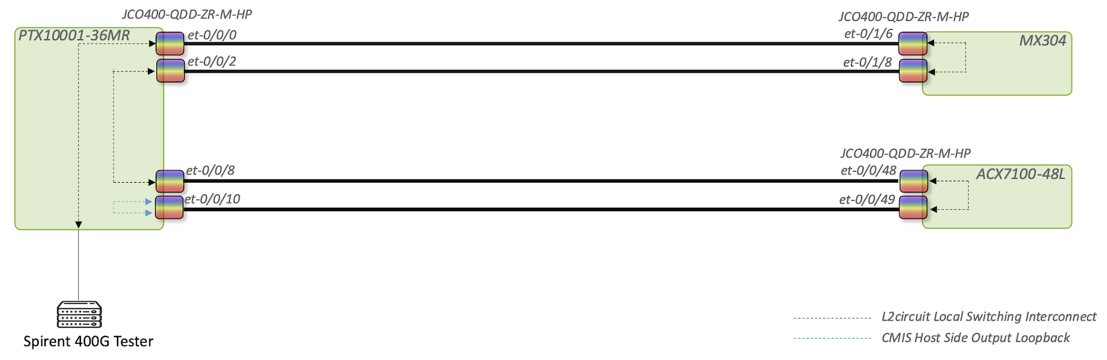
Traffic will go through a snake topology. Router ports are interconnected using l2circuit local switching. At the end of the snake on PTX, the interface is configured as host-side output loopback. In this loopback mode, traffic will be received by the transceiver's DSP and sent back to the media interface again. These loopbacks are defined by CMIS 4.0 and above.
Rx Power per lambda (PTX) = Tx Power (per lambda) - Sum*losses
Rx Power per lambda (PTX) = Tx Power (per lambda) - Mux Loss - VOA Loss - Span Loss -- DeMux Loss
Rx Power per lambda (PTX) = 0dBm - 2dB - 1dB - 0.19dB/km * 75k* - 2dB
Rx Power per lambda (PTX) = 0dBm - 2dB - 1dB - 14.25dB - 2dB
Rx Power per lambda (PTX) = 0dBm - 19.25dB
Rx Power per lambda (PTX) = -19.25dBm
The PTX Side will expect close to -19.25dBm per channel. Not all channels will have the same Rx Power, but it will be close to the calculated value. The Rx Power on all channels will be balanced by setting the initial target Rx Power to -20dBm. This is done by changing the Tx Power per channel on the MX and ACX side.
As of writing this article, JCO400-QDD-ZR-M-HP supports the following 400G OpenZR+ and 400ZR OIF modes. More Host and Media Modes might be supported in the future via Firmware Upgrade.
Host Interface
FEC
Modulation
Symbol Baud Rate
Media Interface
MSA Compliance
1x400G
CFEC
16QAM
59,843,750,000
400ZR
OIF 400ZR IA
4x100G
CFEC
16QAM
59,843,750,000
400ZR
OIF 400ZR IA
1x400G
OFEC
16QAM
60,138,546,798
ZR-400-OFEC-16QAM
OpenZR+ MSA
4x100G
OFEC
16QAM
60,138,546,798
ZR-400-OFEC-16QAM
OpenZR+ MSA
3x100G
OFEC
8QAM
60,138,546,798
ZR-300-OFEC-8QAM
OpenZR+ MSA
2x100G
OFEC
QPSK
60,138,546,798
ZR-200-OFEC-QPSK
OpenZR+ MSA
1x100G
OFEC
QPSK
30,069,273,399
ZR-100-OFEC-QPSK
OpenZR+ MSA
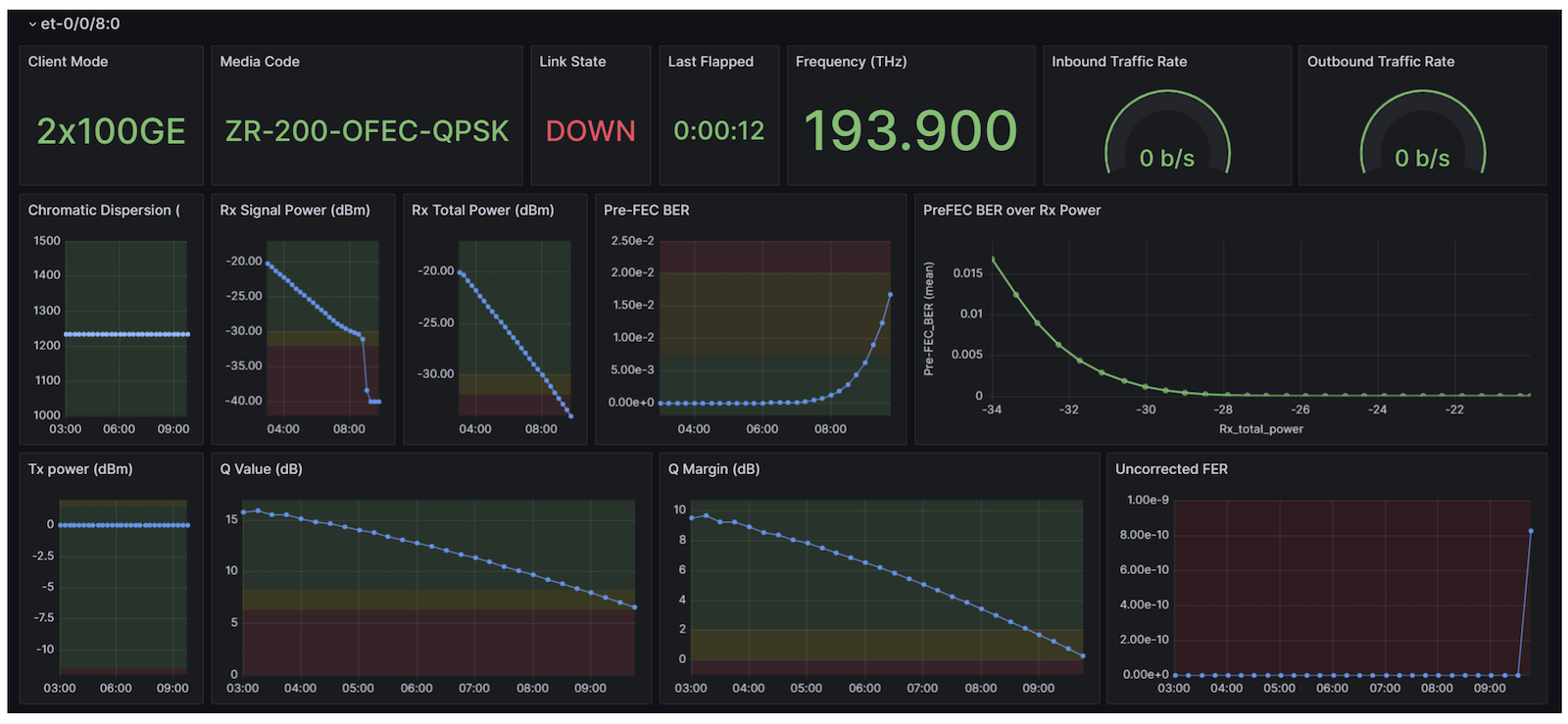
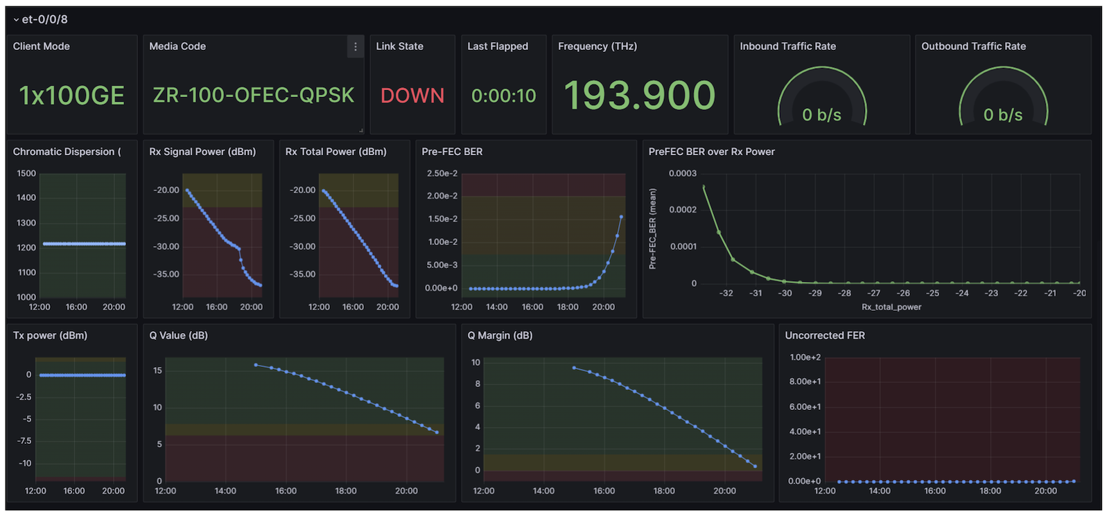
In this post, we will test the different OpenZR+ Media Interfaces namely: ZR-400-OFEC-16QAM, ZR-300-OFEC-8QAM, ZR-200-OFEC-QPSK, and ZR-100-OFEC-QPSK. Each Media Interface will have different RX Sensitivity due to the different modulation and/or symbol rates.
This section will cover the configurations needed to deploy ZR/ZR+ transceivers. For the configurations used for testing, refer to the Extensive Router Configuration Section of this article.
The transceivers under test are the ones inserted in PTX10001-36MR. Initially, the TX Power on MX304 and ACX7100-48L will be adjusted to have a target Rx Power of -20dBm.
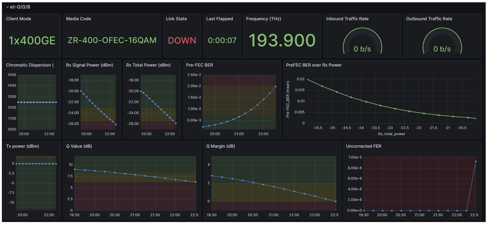
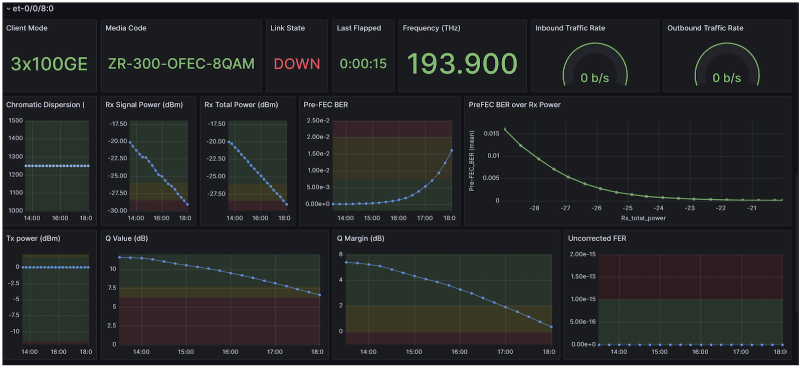
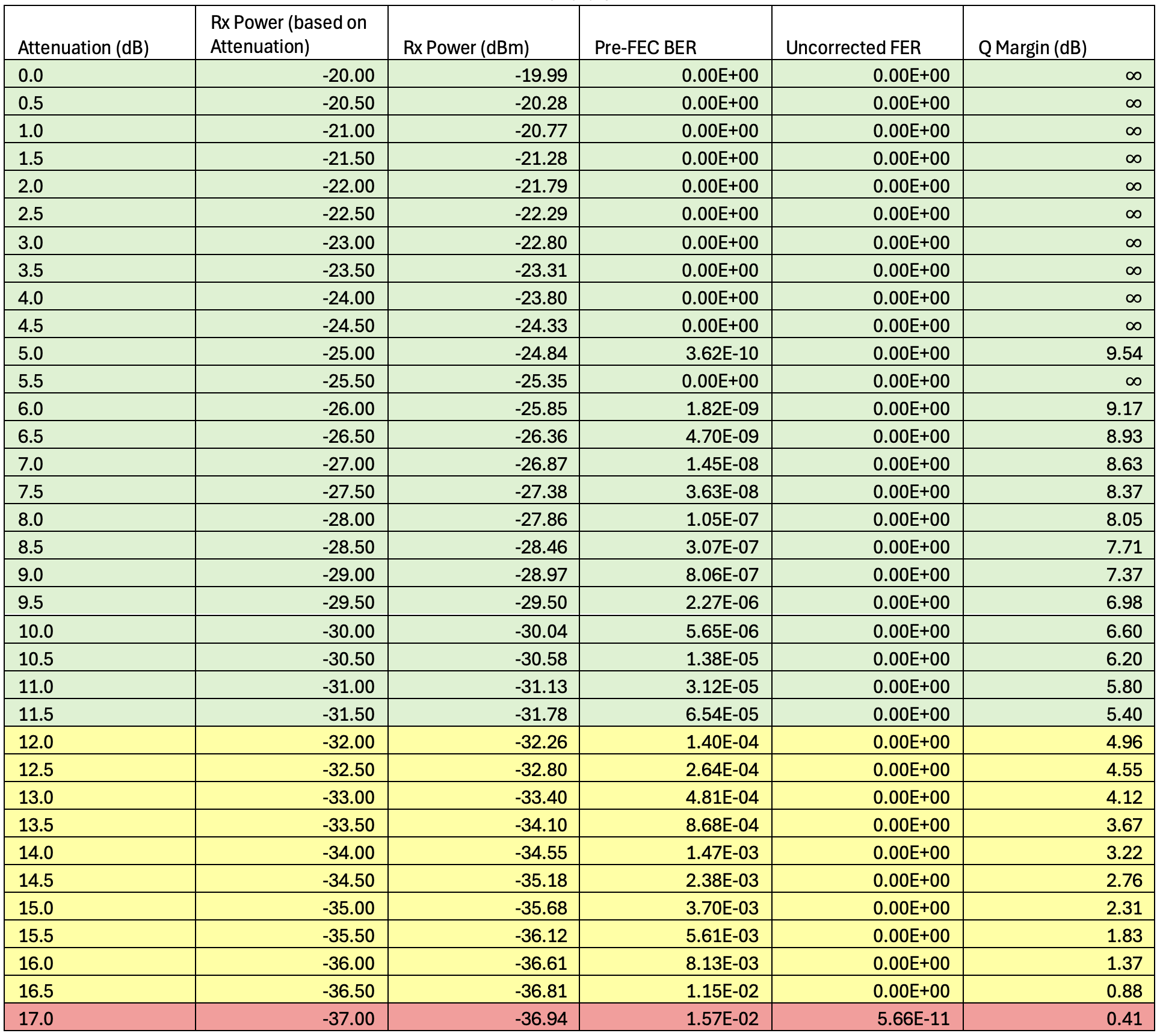
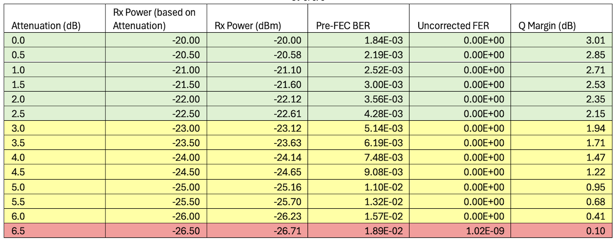
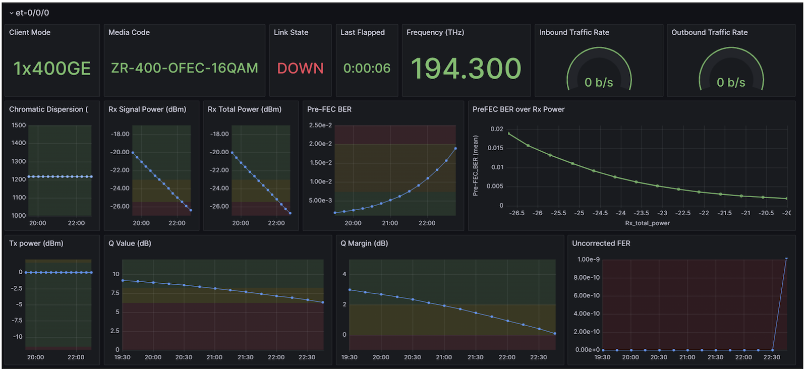
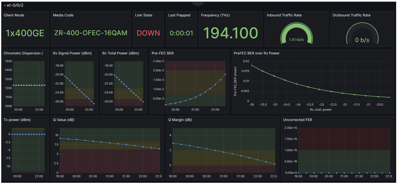
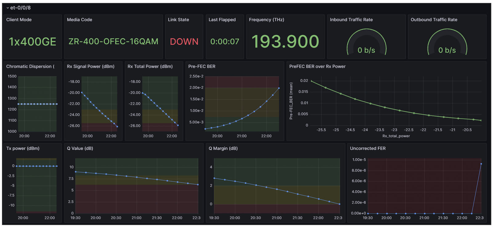
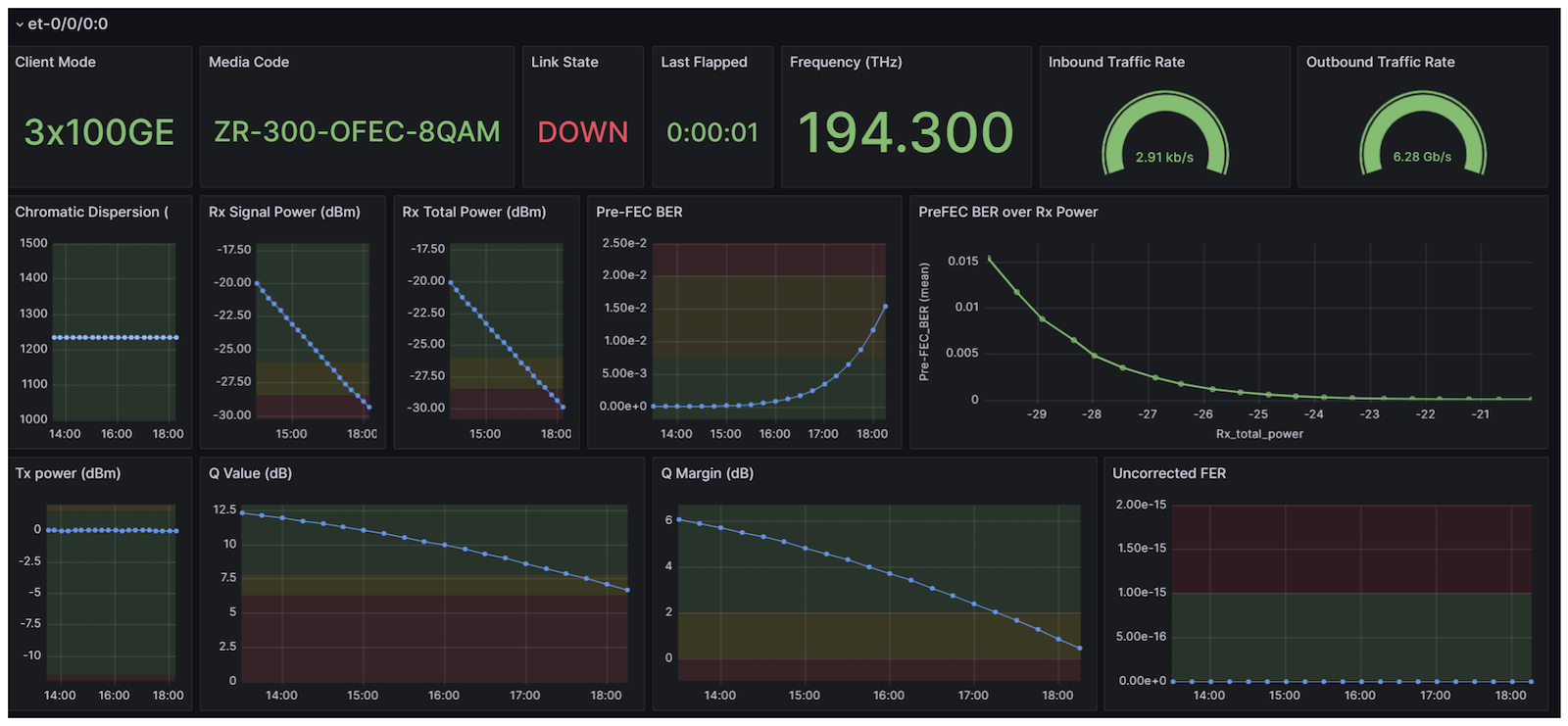
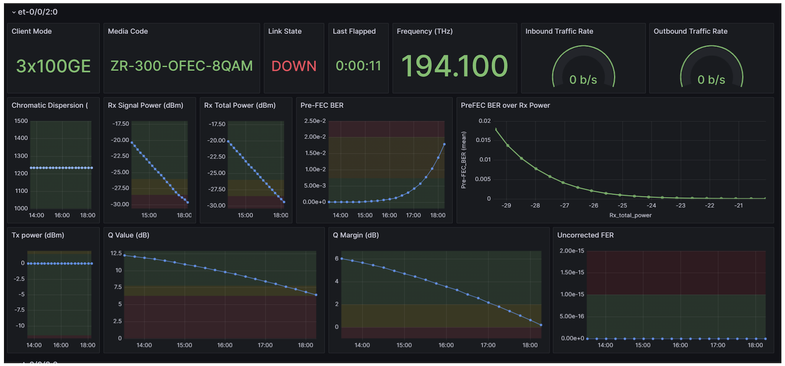
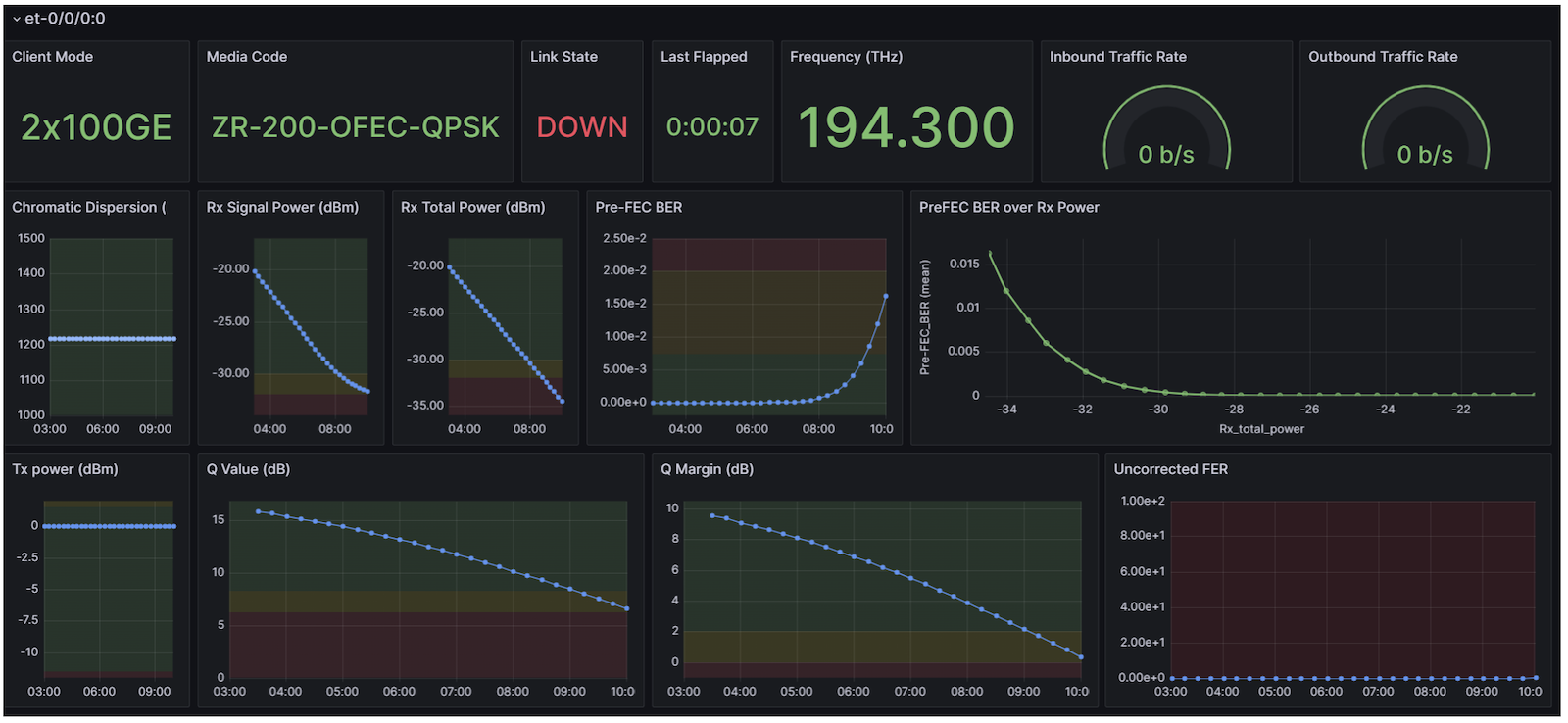
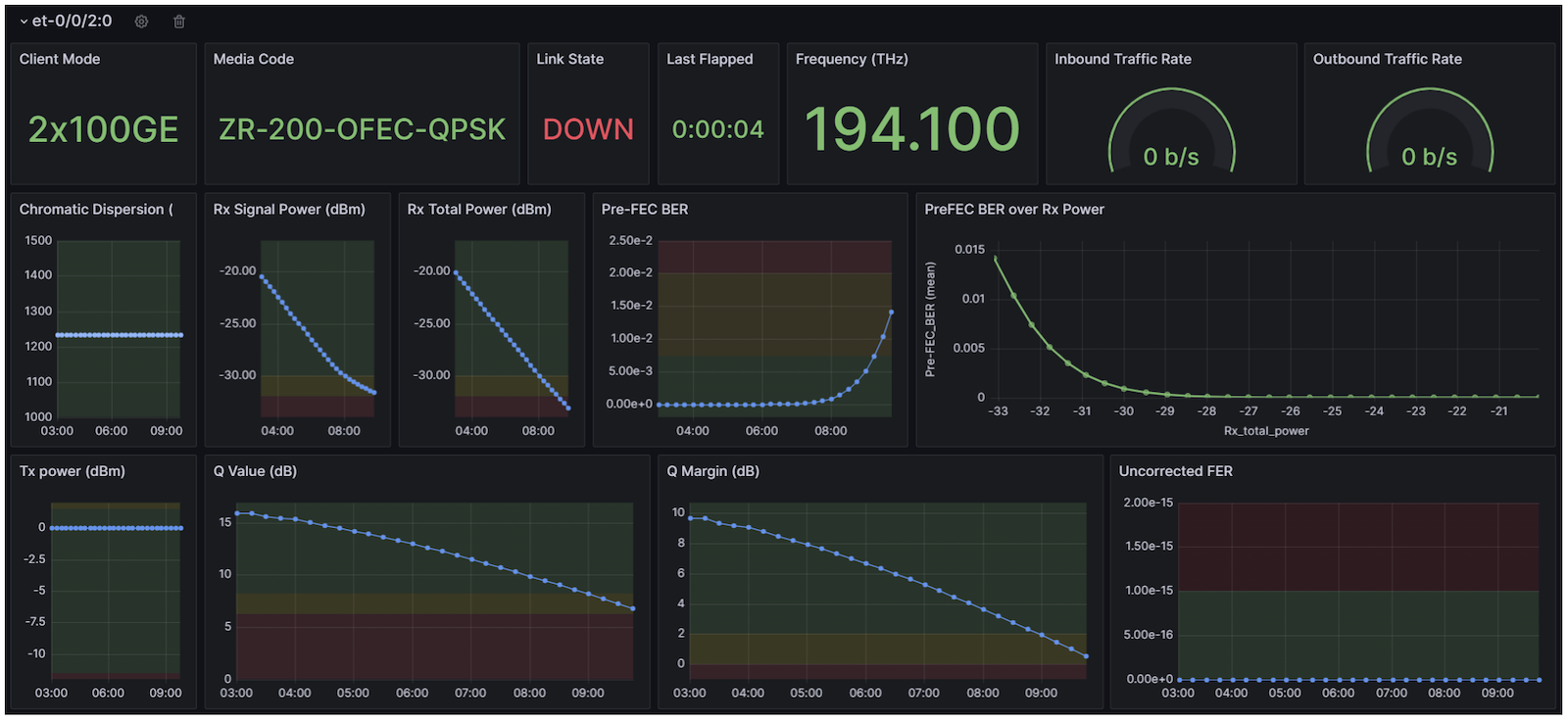
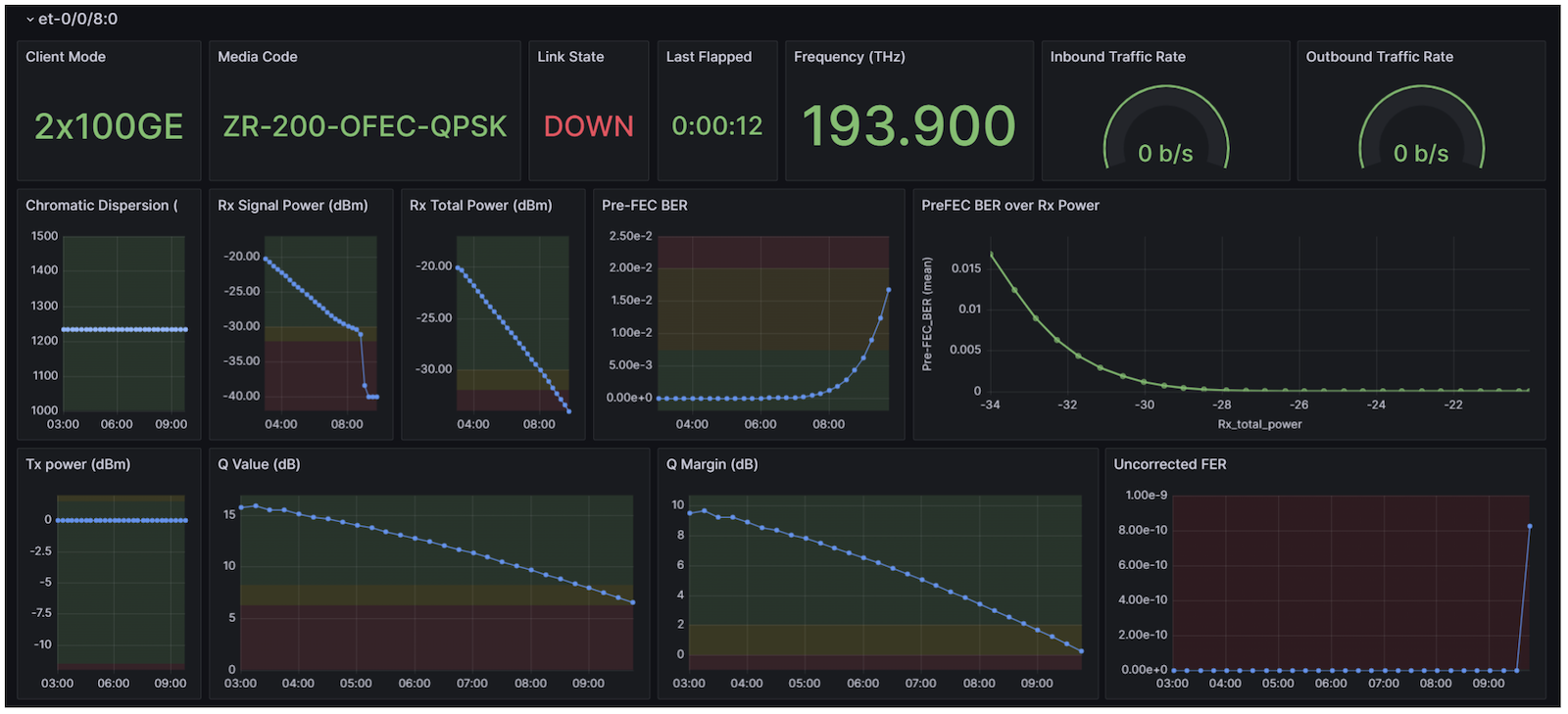
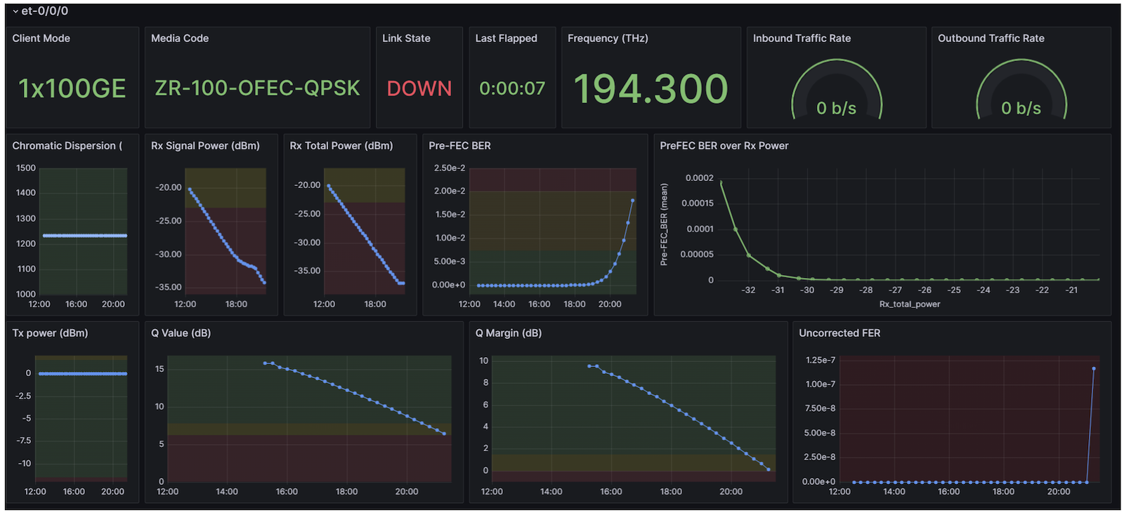
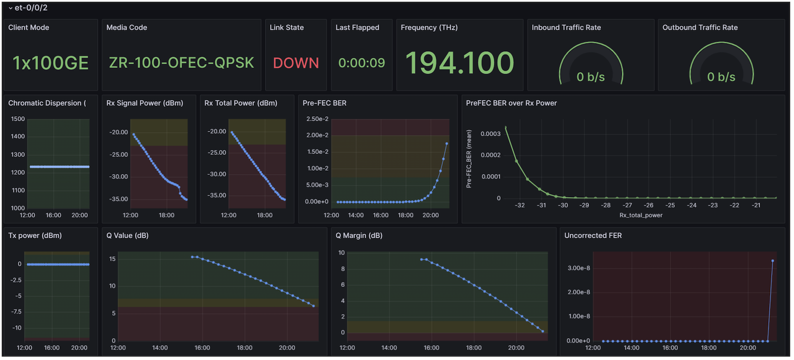
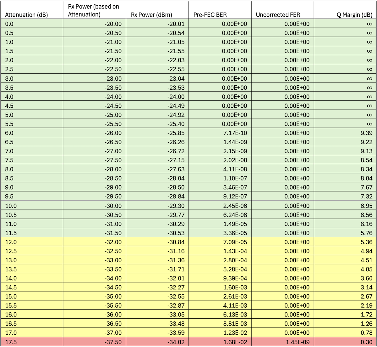
A Python script is set up to run every 15 minutes (XX:00, XX:15, XX:30, XX:45). The script will start at 0dB attenuation. The script will capture the Versatile Diagnostics Monitoring (VDM) or Performance Monitoring (PM) from all interfaces being tested at the end of every 15-minute interval.
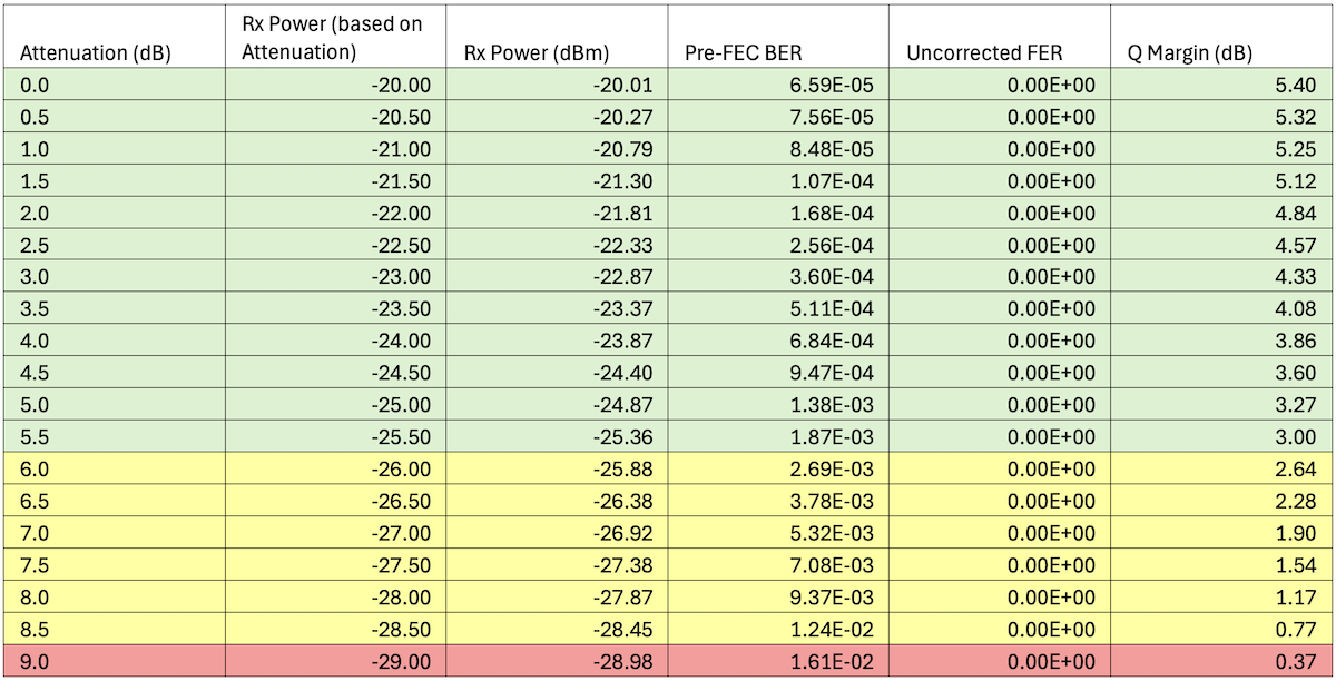
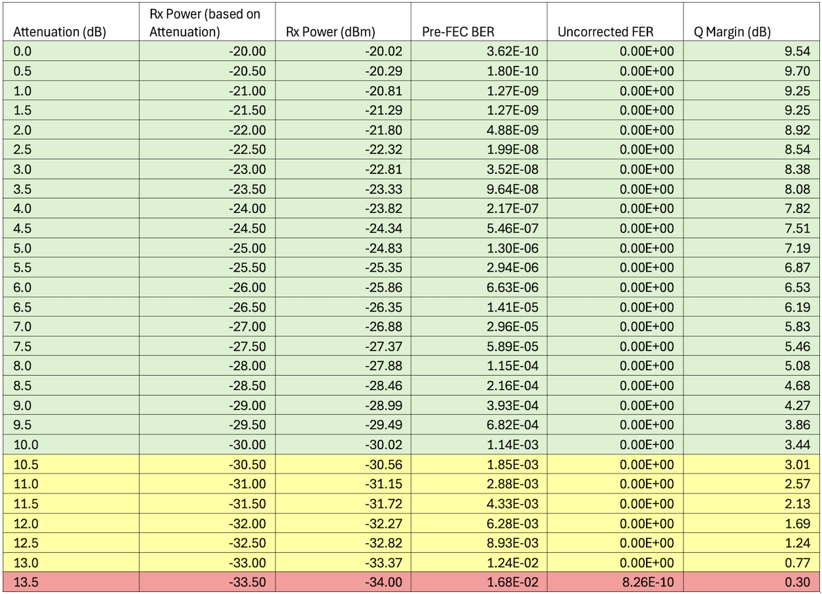
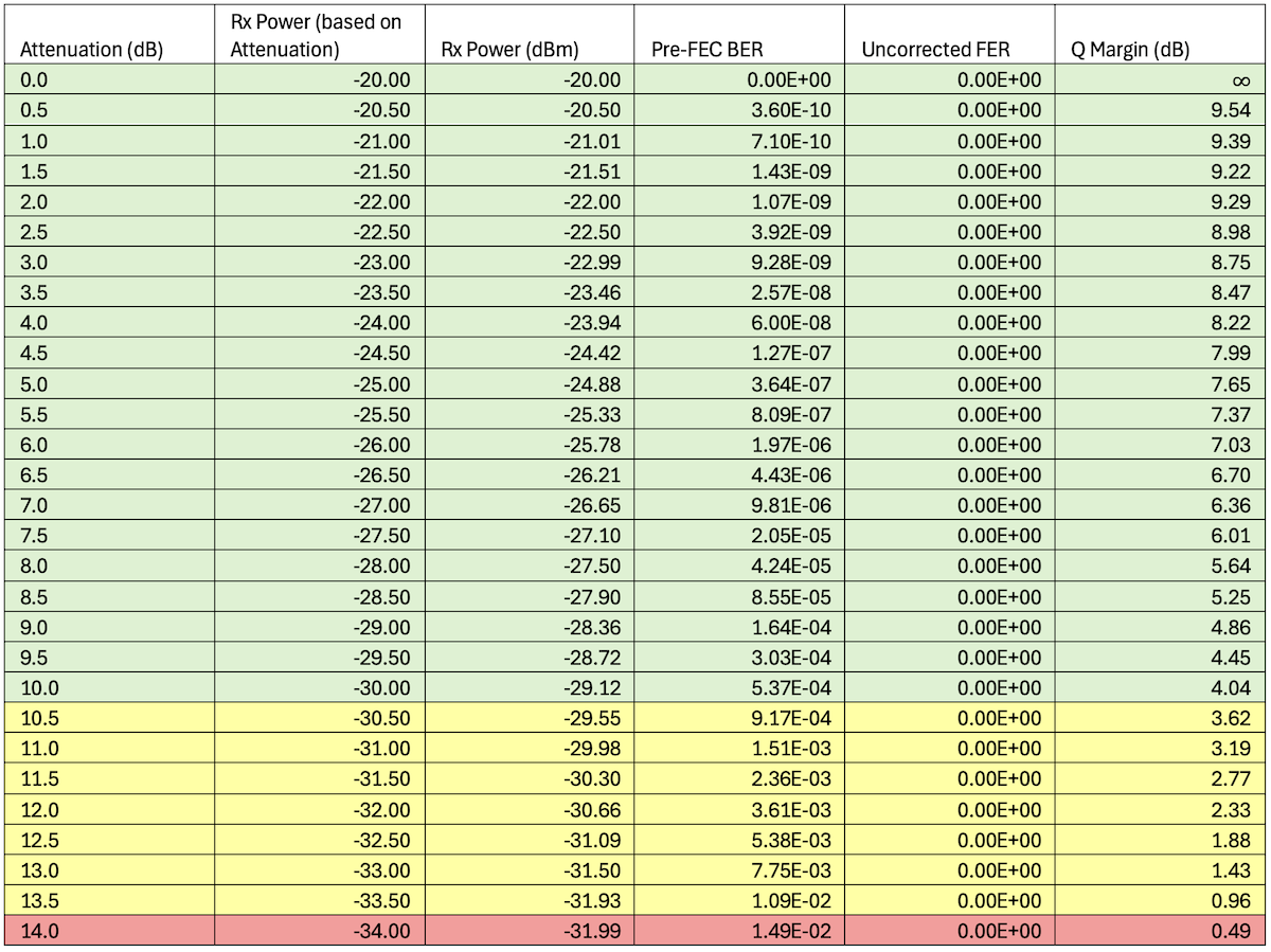
After capturing the data, the script will increase the attenuation by 0.5dB, capture the data at the end of the 15-minute interval, and repeat until all channels are down.
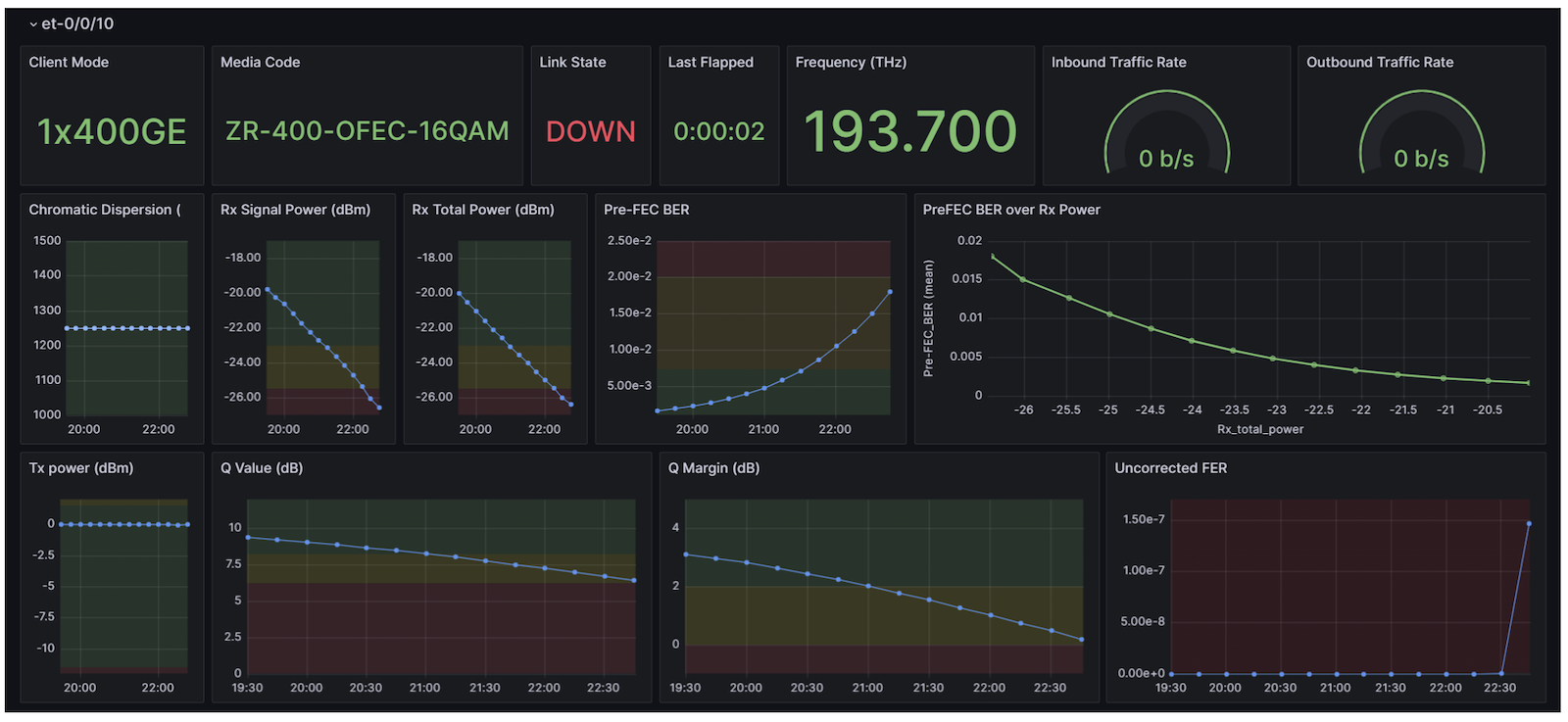
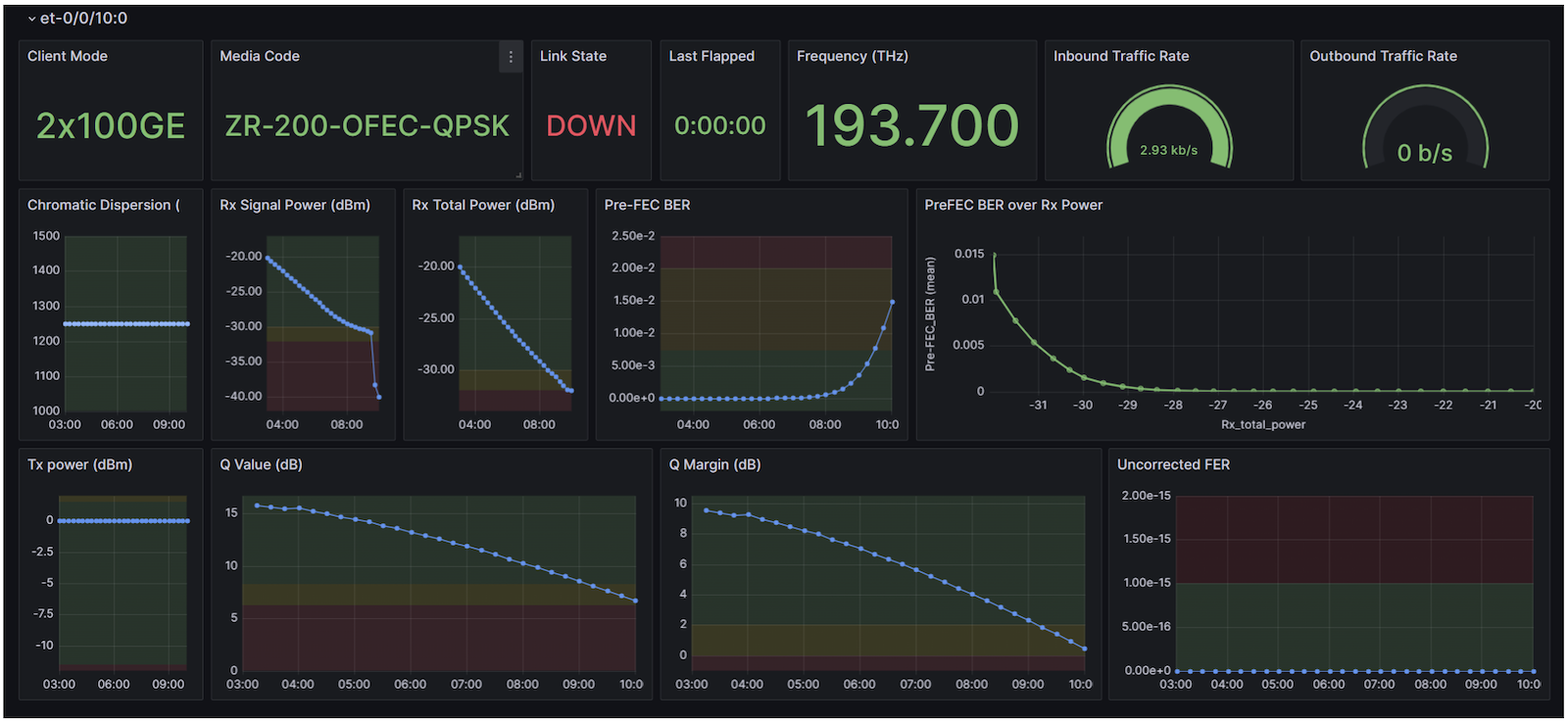
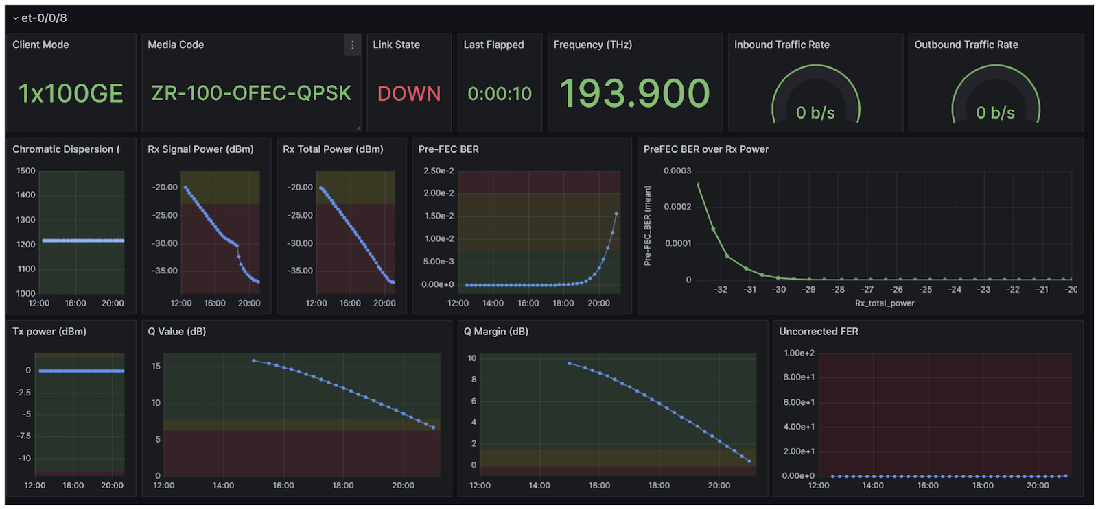
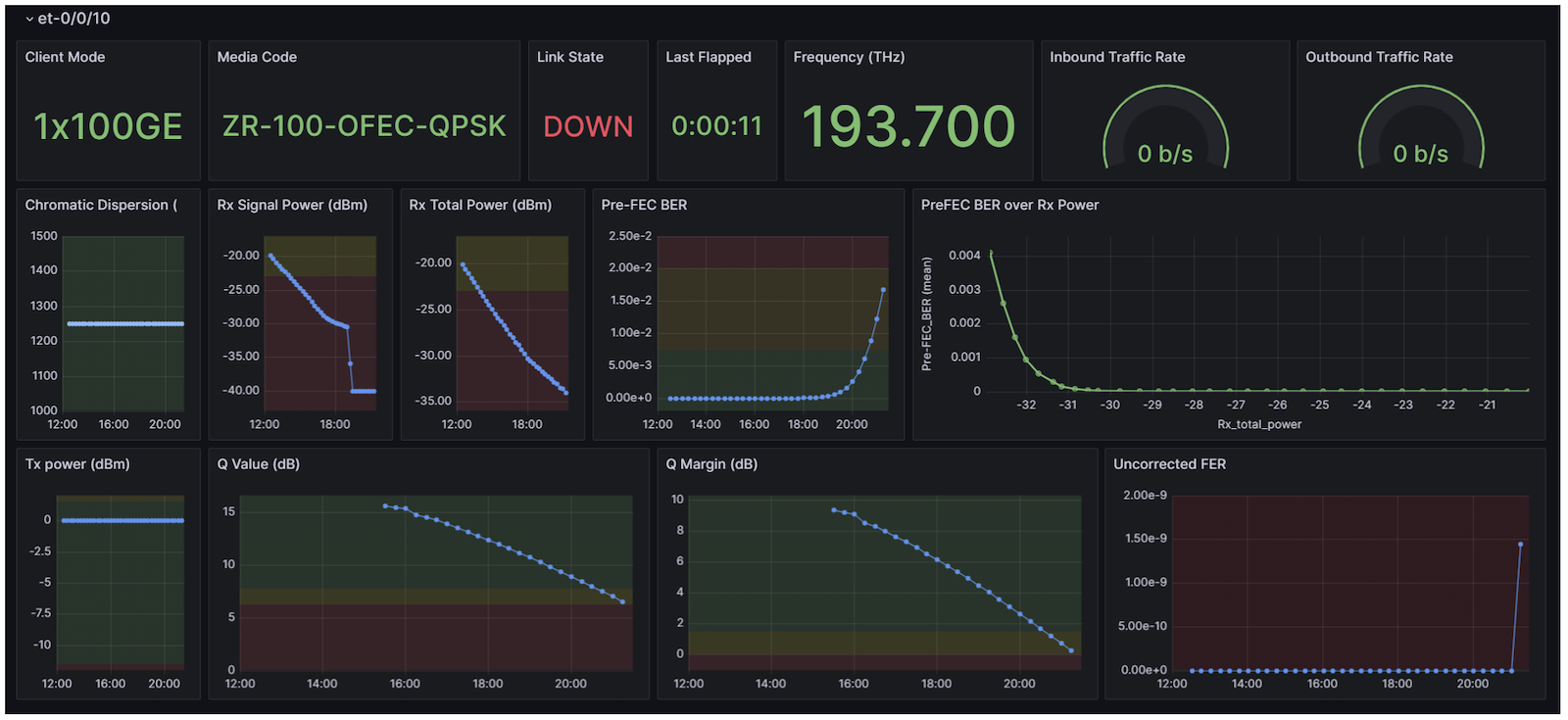
The captured VDM/PM will be the average Pre-FEC BER, Uncorrected FER, and Rx Power. The captured data will be saved on InfluxDB and visualized by Grafana. This is based on IPoDWDM-TIG. The Python script and Grafana Dashboard were modified for the test procedures.
For more information on how the router collects VDM please refer to the More Information Section of this article.
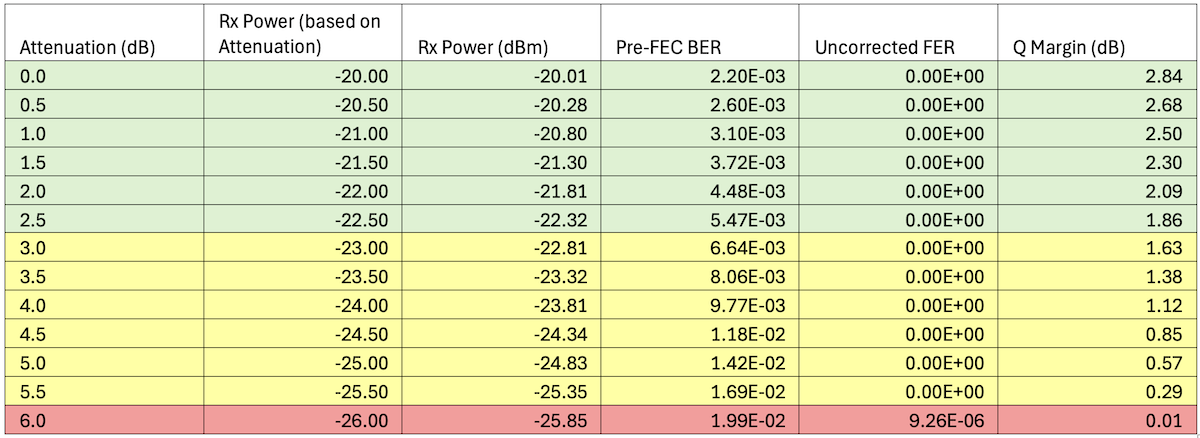
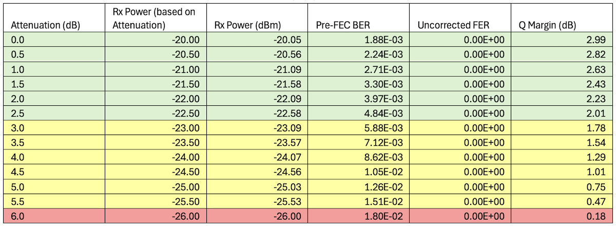
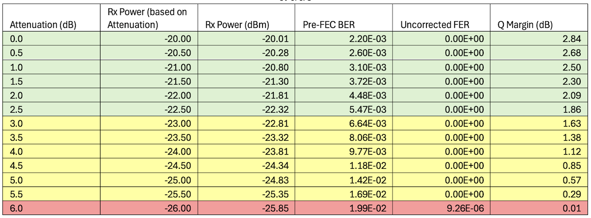
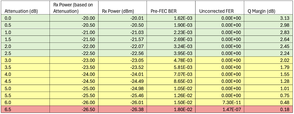
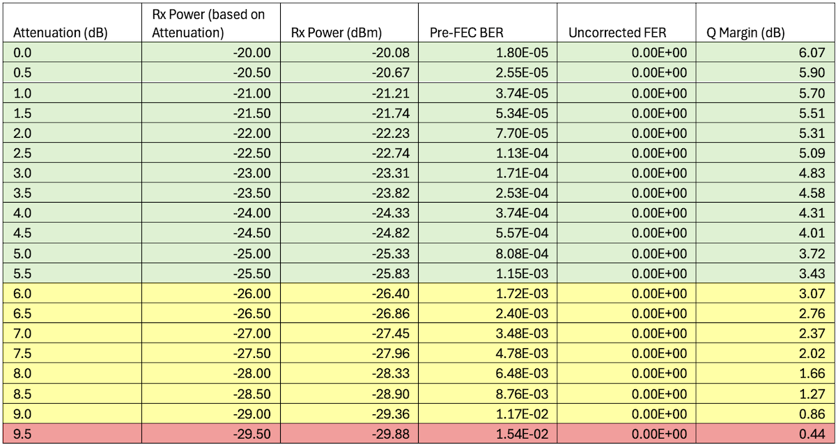
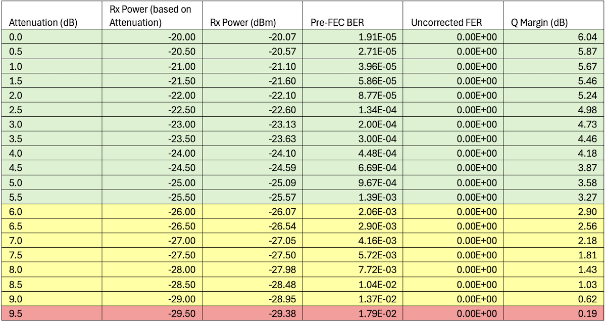
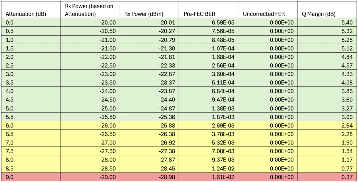
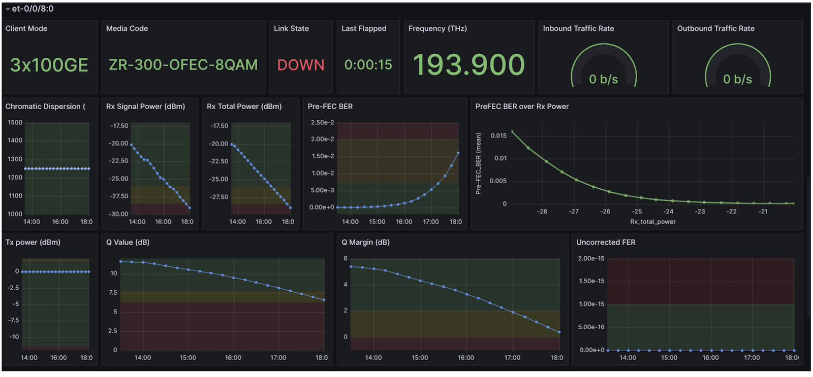
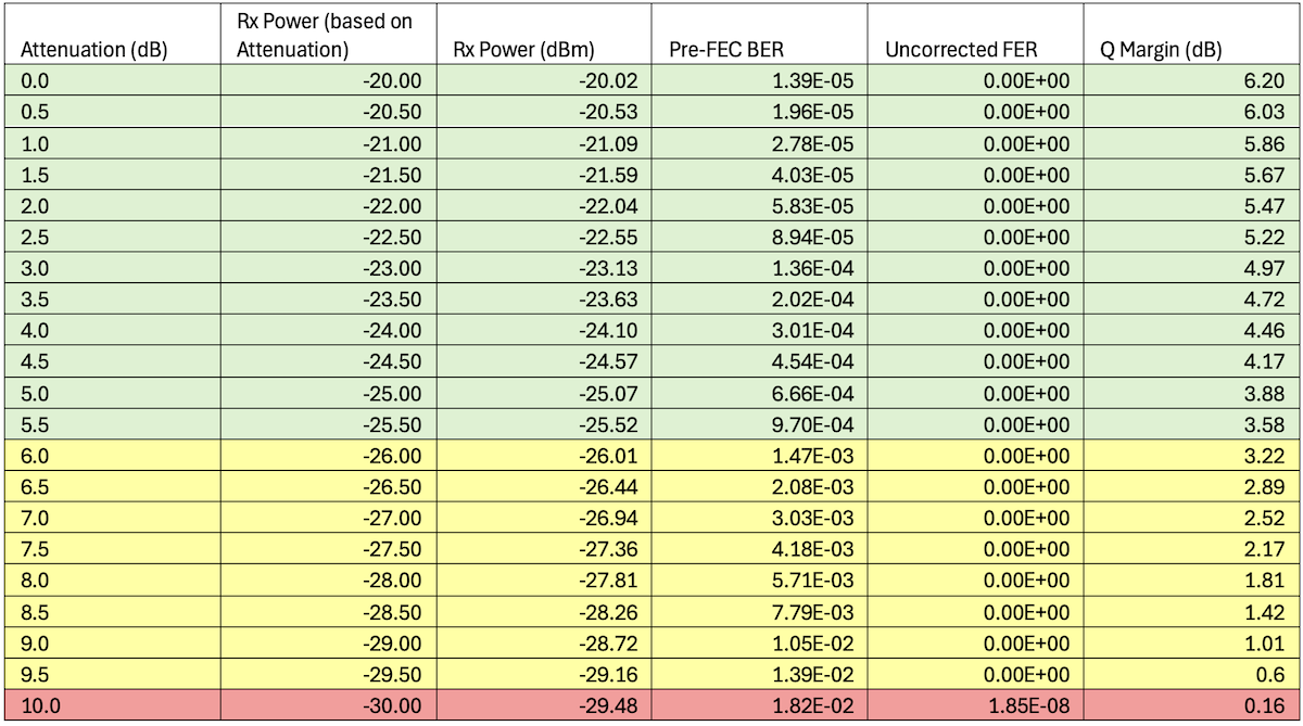
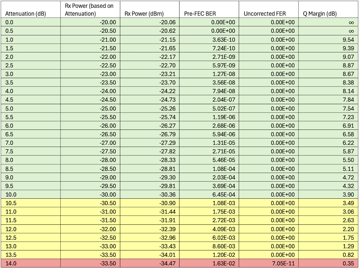
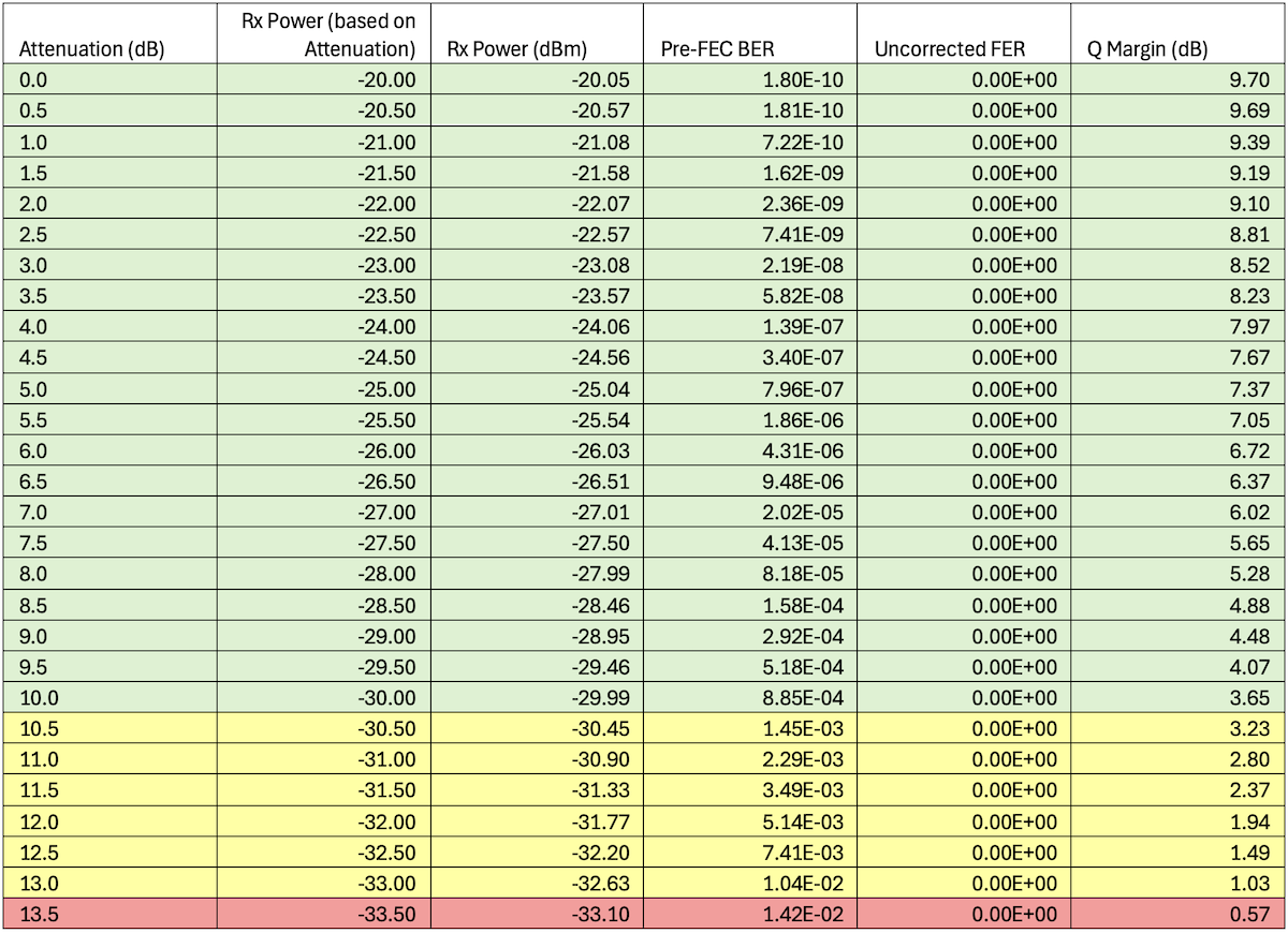
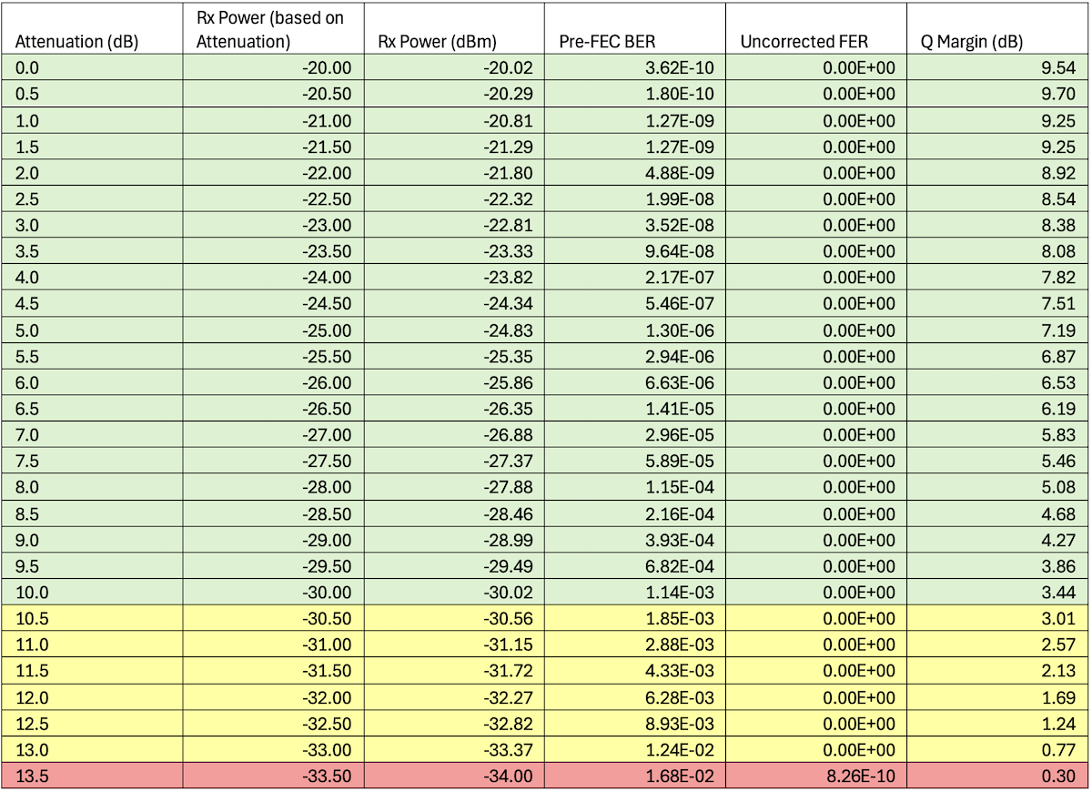
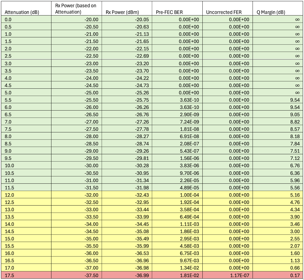
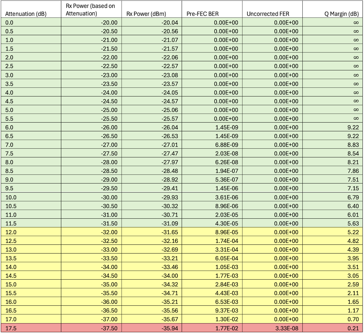
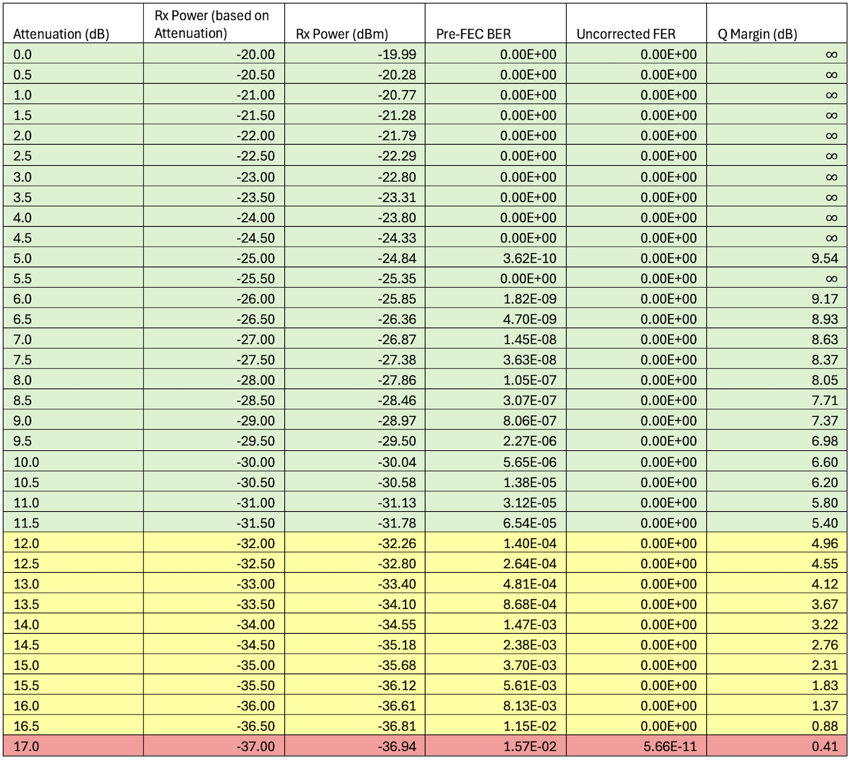
Columns highlighted yellow indicate that the Rx Power is below the advertised Rx Sensitivity. The column highlighted ** in red ** indicates that the channel is down.
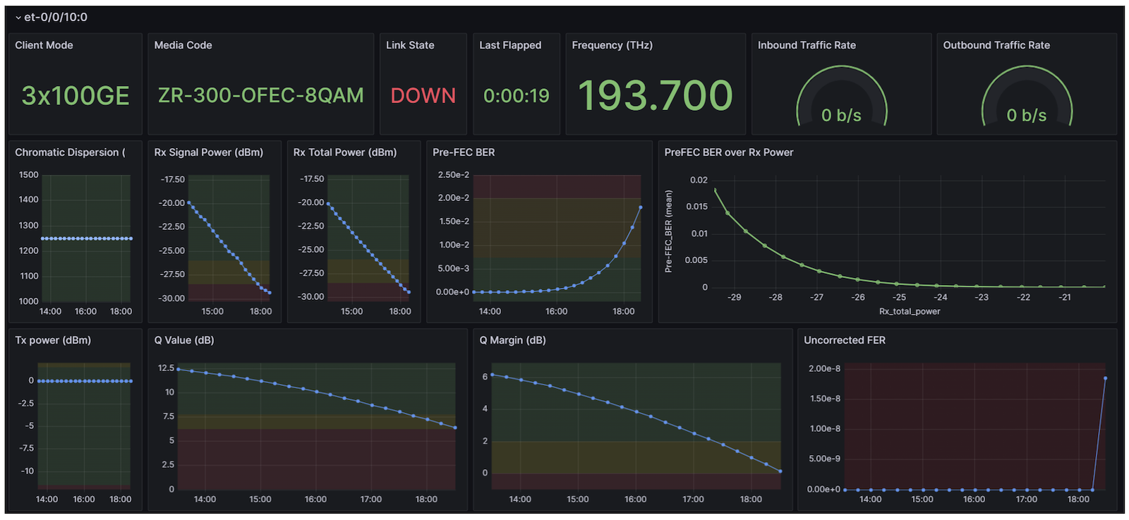
For brevity, only et-0/0/8, the worst-performing transceiver is shown. For the rest of the results, go to the "Extensive Results" section of this article.
Mux/DeMux or Multiplexer/Demultiplexer is a passive optical component that is used to aggregate multiple WDM signals into a single pair of fiber optic cables. The multiplexer component aggregates multiple wavelengths of light into a single fiber. The demultiplexer separates them back to separate wavelengths. For example, ADTRAN 8CSM+#19430-#19290 is an 8-channel Mux/DeMux with 200GHz Grid spacing. It can carry 3.2Tbps using 400G transceivers or 6.4Tbps using 800G transceivers. This component has a 2dB Insertion Loss.
The transceivers have a feature called Versatile Diagnostics Monitoring. VDM parameters are observables that are useful for diagnostics and performance monitoring. The router polls the transceivers every second. The router then stores the measurements into two bins: a 15-minute bin, and a 1-day bin. Customizable interval bins might be supported in later releases.
The 15-minute bin begins at the 00th, 15th, 30th, and 45th of the hour. The 1-day bin begins at 00:00-UTC. These bins will have the maximum, minimum, and average values for the whole bin's interval. The 15-minute average values are used for the tests done in this article.
Dashboards can be created to visualize these PM metrics. An example is this IPoDWDM-TIG.
Other PM metrics used in this article are Q-Value and Q-Margin. It is a metric to measure the quality of an optical link. It is directly calculated from the Pre-FEC BER.
The Q-Value and Q-Margin are manually calculated by the Python Script used in this test as the transceiver does not support these PM metrics yet. These will be supported when the transceivers are upgraded to support C-CMIS 1.3.
The following formula can be used to calculate the distances that can be achieved.
Figure 12: Formula
JCO400-QDD-ZR-M-HP has Tx Power = 0dBm and 4 different Rx Sensitivities depending on the Media Interface mode used.
ZR-400-OFEC-16QAM has RX Sensitivity of -23dBm,
ZR-300-OFEC-8QAM is -26dBm,
ZR-200-OFEC-QPSK is -30dBm,
ZR-100-OFEC-QPSK is -32dBm.
Mux Loss and DeMux Loss vary by the number of channels. Typically, the Mux and DeMux losses are equal. 8-channel mux/demux typically have 2dB loss, 48-channel mux/demux typically have 5.5dB loss, and 64-channel mux/demux typically have 6.5dB loss.
As a guidance, the below table shows the distances that can be achieved using different combinations of numbers of channels and media interface modes.
Let: Fiber Loss Coefficient = 0.25dB/km, Margin = 0
Note 1: For MX Series and PTX10003, the speed and number-of-sub-ports are configured on the chassis level rather than the interface level. The optics-options are still configured on the interface level.
Note 2: For channelized interfaces, optics-options are configured on the first sub-port NOT on the parent port.
Note 1: For MX Series and PTX10003, the speed and number-of-sub-ports are configured on the chassis level rather than the interface level. The optics-options are still configured on the interface level.
Note 2: For channelized interfaces, optics-options are configured on the first sub-port NOT on the parent port.
Note: For MX Series and PTX10003, the speed and number-of-sub-ports are configured on the chassis level rather than the interface level. The optics-options are still configured on the interface level.