Service providers and large enterprise networks nowadays offer multiple services with different traffic criteria, e.g., high bandwidth, moderate bandwidth with moderate latency, and small bandwidth with latency-sensitive requirements, etc. These requirements are also commonly used for 5G transport network slicing in IP networks. To meet the demand, using LSP (RSVP-TE, SR-TE, or SRv6-TE) is one of the solutions.
Manual CLI configuration is time-consuming and requires a high level of operational and maintenance expertise. We need to configure every ingress router and ensure the LSP paths are reachable from every router. The strict LSP path creation also complicates the network engineer to be absolutely aware of the hop-by-hop path (i.e., P2P IP, loopback IP, adj-SID, node-SID, etc., depending on what technology is being used in the network) from the ingress to the egress router. Imagine a customer willing to add multiple nodes to expand their network, they need to manually configure numerous routers to create new LSPs tunnels between the existing and the new nodes.
Juniper Routing Director (RD), formerly known as Paragon Automation, is built to solve this problem. It automates the LSP creation, but also the traffic steering based on defined constraints. The automation could be done via PCEP or NETCONF. RD is a multi-vendor solution by nature, hence it can also automate and monitor third-party hardware. However, I will only focus on Juniper router in this Techpost article.
You may head to this article [1], if you want to learn more about RD.
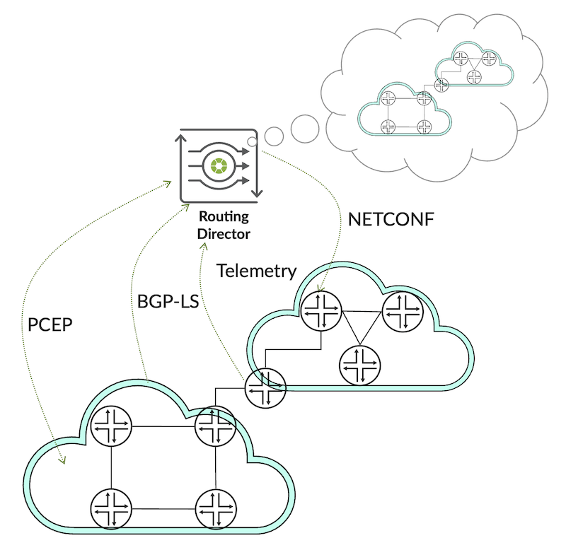
The high-level topology below describes how the routers communicate with RD:
Figure 1: Logical Connection Infrastructure
There are some essential key protocols to enable the communication:
BGP-LS (BGP Link State): this connection is required for Routing Director to learn the full IGP topology, metric, bandwidth, delay, Segment-ID information and many more. BGP-LS is a standard defined on RFC8571.
PCEP (Path Computation Element Protocol): protocol used between routers, or Path Computation Client, and the Routing Director (Path Computation Element). PCEP is based on RFC5440 and the PCEP extension function is defined in RFC8231 (Stateful-PCE), RFC8281(PCE-Initiated LSP), SR-PCE ,etc.
NETCONF (Network Configuration Protocol) over SSH: provides fine-grained structured configuration management. In this case, routers are NETCONF servers and RD is the NETCONF client. NETCONF is a standard based on RFC6241.
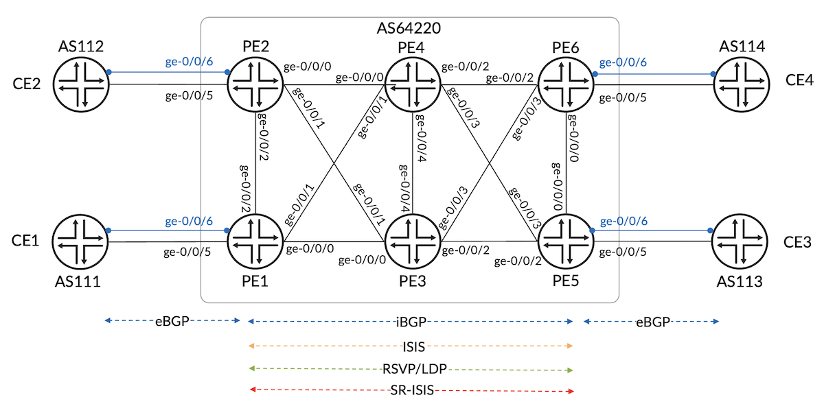
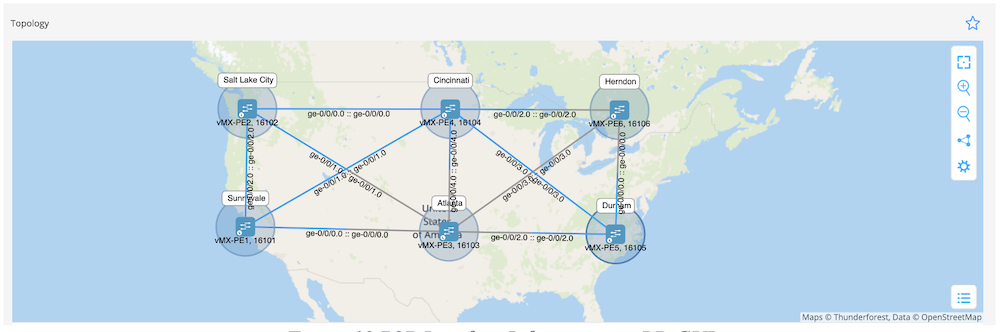
I will use the same topology (figure 2) than my previous Techpost article (Service Orchestration in RD) with the addition of SR-MPLS (ISIS) as an underlay protocol. If you have not read it yet, please go here.
Figure 2: Network Topology
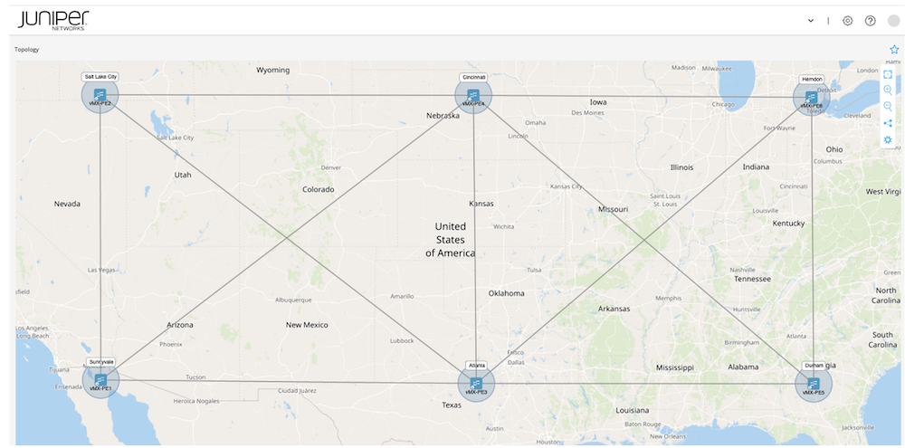
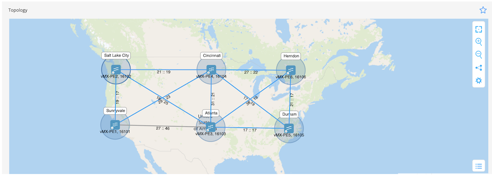
RD offers real-time topology discovery by BGP-LS. When the devices are connected by IGP, the topology can be visualized on the GUI depicted in Figure 3. Routing Director 2.5 (Figure 4) and Junos 23.4R1.9 are used in this demonstration.
jcluser@vMX-PE1> show version
Hostname: vMX-PE1
Model: vmx
Junos: 23.4R1.9
JUNOS OS Kernel 64-bit [20231122.ee0e992_builder_stable_12_234]
JUNOS OS libs [20231122.ee0e992_builder_stable_12_234]
JUNOS OS runtime [20231122.ee0e992_builder_stable_12_234]
[...]
Let's verify the prerequisite connectivity from the router perspective.
jcluser@vMX-PE1> show configuration system services
netconf {
    ssh {
        rate-limit 20;
    }
}

jcluser@vMX-PE1> show system connections | match 2200
tcp4       0      0  100.123.1.4.62479                             100.123.42.100.2200                           ESTABLISHED


[...]
Since all prerequisite protocols are clear, let's head up to the use cases.
The objective is to demonstrate that RD could automate the creation of two active paths using different links from ingress to egress. Diversity tunnel is commonly used for critical service that has strict requirements for resiliency.
I will create diversity tunnels from PE1 to PE6 for this use case.
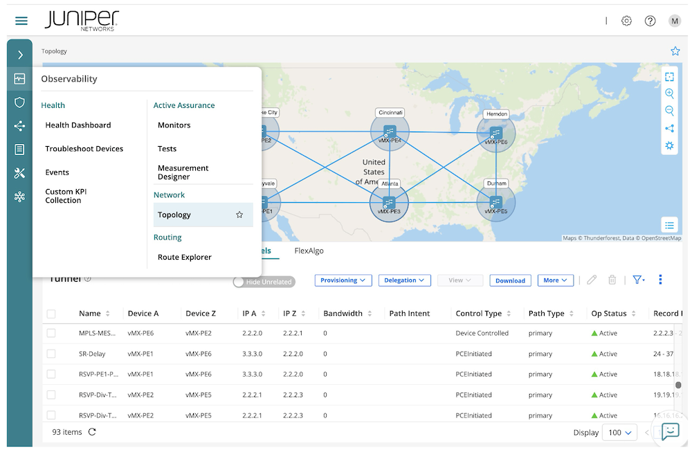
First, we need to go to Observability --> Network --> Topology.
Figure 5: - RD Topology GUI
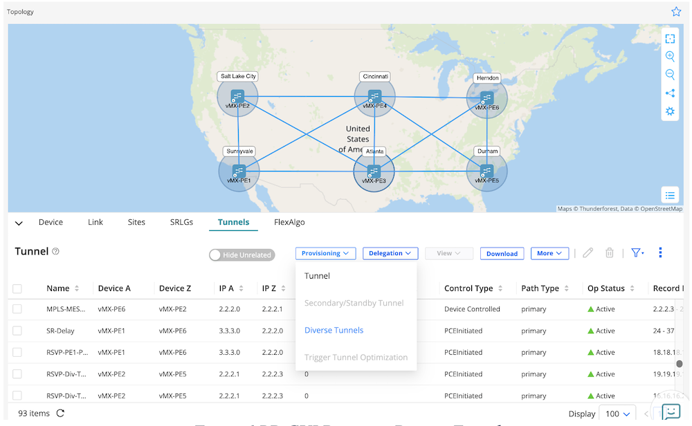
Then, we go to the Tunnels tab to create the Diverse Tunnels.
Figure 6: - RD GUI Provision Diverse Tunnel
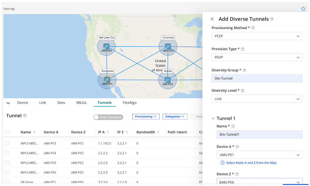
We define the following variables in the GUI:
Provisioning Method: PCEP
Provision Type: RSVP
Diversity Group: Div-Tunnel
Diversity Level: Link
Tunnel 1 Name: Div-Tunnel1
Device A: vMX-PE1
Device Z: vMX-PE6
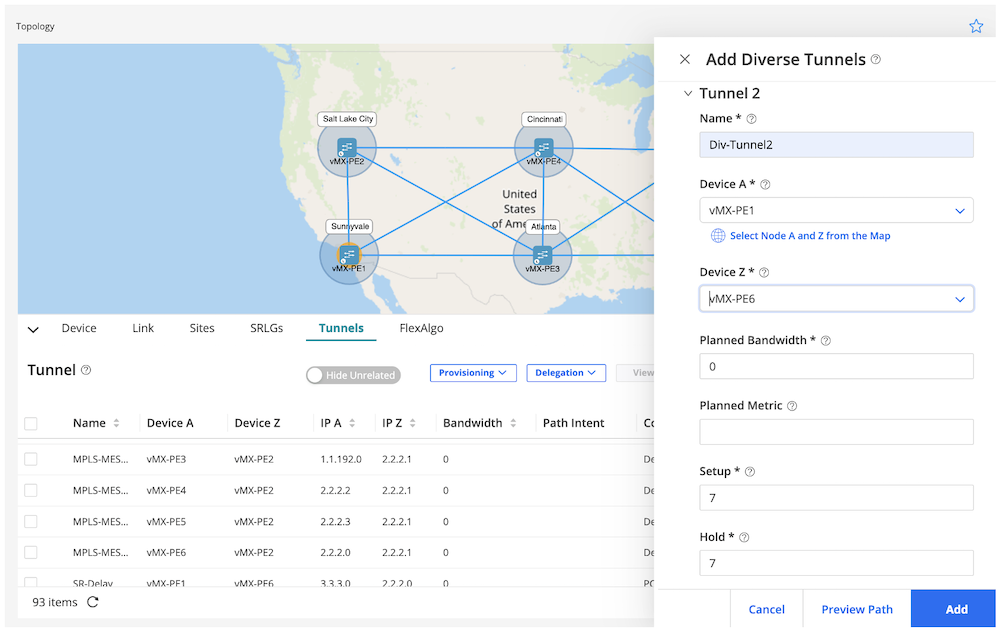
Tunnel 2 Name: Div-Tunnel2
Device A: vMX-PE1
Device Z: vMX-PE6
And the click "Add"
Figure 7: - Variable Definition for Diverse Tunnel (1)
Figure 8: - Variable Definition for Diverse Tunnel (2)
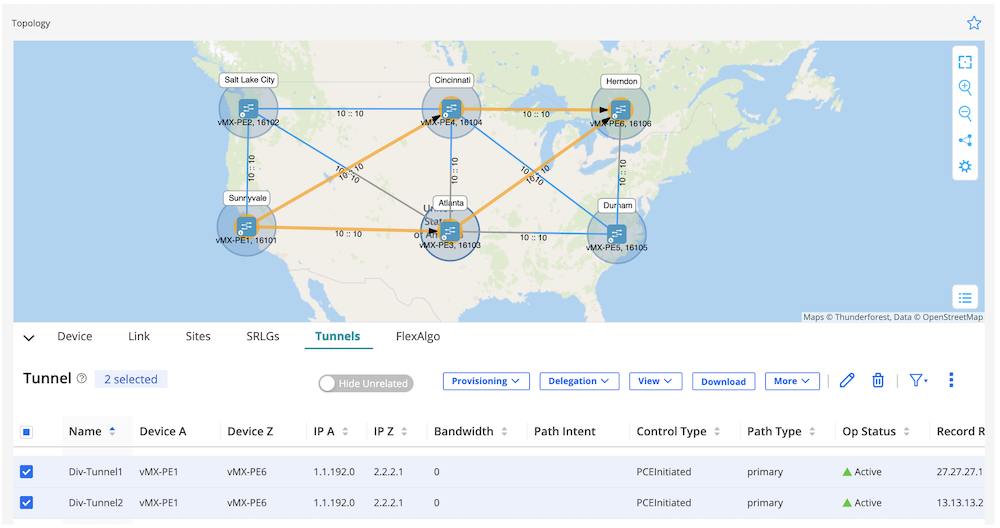
We see in that the tunnels were successfully created with different paths.
jcluser@vMX-PE1# show | compare
[edit groups paragon-service-orchestration interfaces ge-0/0/0]
+   disable;

jcluser@vMX-PE1# commit and-quit
warning: Could not connect to re1 : No route to host
warning: Cannot connect to other RE, ignoring it
kenv: unable to get vmtype
commit complete
Exiting configuration mode

jcluser@vMX-PE1> show isis adjacency
Interface             System         L State         Hold (secs) SNPA
ge-0/0/0.0            vMX-PE3        3  Down                   0
ge-0/0/1.0            vMX-PE4        3  Up                    26
ge-0/0/2.0            vMX-PE2        3  Up                    25
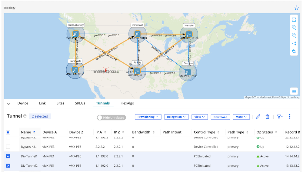
Figure 11: - Tunnel Diversity Path After Simulate Fibre Cut
We can see the result in figure 11: RD will announce two important things:
Link between PE1 and PE6 is declared down and a dotted line with "F" (Fail) link is represented in the topology GUI. It will not being used for traffic.
Div-Tunnel1 LSP initially used the PE1 >< PE3 link. It's now rerouted through other path (in this demo to PE1 >< PE2 link) and we still maintain the link diversity constraint with Div-Tunnel2 LSP.
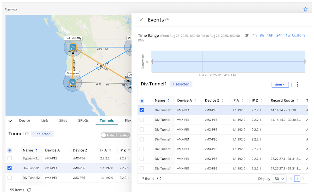
Furthermore, starting from RD2.5, we can track the tunnel changes with complete detailed information, including timestamp and record route.
Figure 12: Tunnel Events History
2. RSVP-TE Netconf tunnel creation and delegation
Let's demonstrate we can create an RSVP-TE tunnel and associate it with the CLI configuration. This will result in the control type from RD GUI being "Device Controlled". The LSP is initiated from RD but is statically controlled by the router itself.
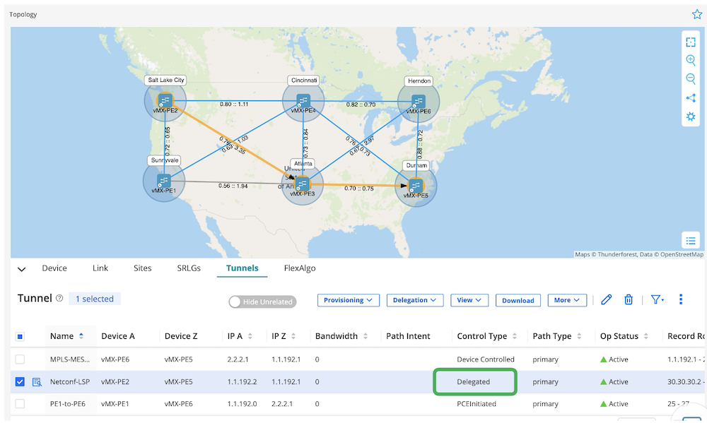
We can delegate it to RD after the LSP is successfully created. The RD will take control of the LSP, the control type becomes "Delegated".
I will create a tunnel from PE2 to PE5 for this use case.
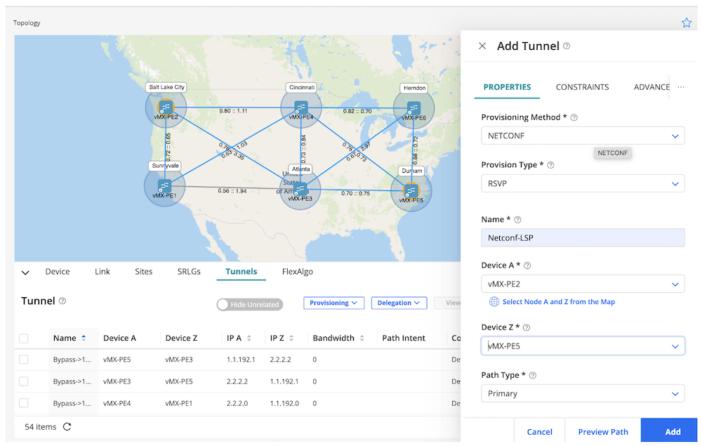
First, we go to Tunnels --> Provisioning and we define key variables in the GUI:
Provisioning Method: NETCONF
Provision Type: RSVP
Name: Netconf-LSP
Device A: vMX-PE2
Device B: vMX-PE5
Routing Method: Routed by Device
Figure 13: - RD GUI for NETCONF Tunnel Provisioning Flow
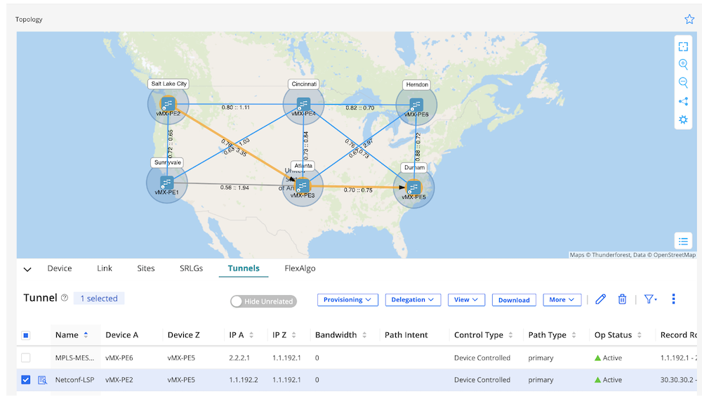
Click Add after finishing defining everything.
Figure 14: - Netconf-LSP Successfully Created
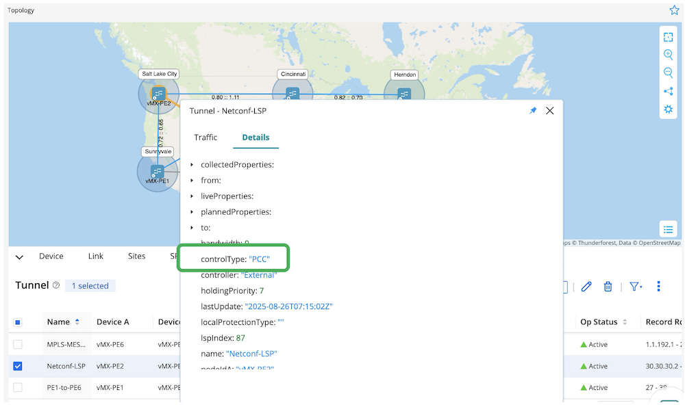
Figure 15: - control Type: PCC Information from RD GUI
We can see in and that the LSP has been successfully created.
jcluser@vMX-PE2> show mpls lsp ingress
Ingress LSP: 6 sessions
To              From            State Rt P     ActivePath       LSPname
1.1.192.0       1.1.192.2       Up     0 *                      MPLS-MESH-from-vMX-PE2-to-vMX-PE1
2.2.2.2         1.1.192.2       Up     0 *                      MPLS-MESH-from-vMX-PE2-to-vMX-PE3
2.2.2.0         1.1.192.2       Up     0 *                      MPLS-MESH-from-vMX-PE2-to-vMX-PE4
1.1.192.1       1.1.192.2       Up     0 *                      MPLS-MESH-from-vMX-PE2-to-vMX-PE5
2.2.2.1         1.1.192.2       Up     0 *                      MPLS-MESH-from-vMX-PE2-to-vMX-PE6
1.1.192.1       1.1.192.2       Up     0 *     Netconf-LSP      Netconf-LSP

jcluser@vMX-PE2> show configuration protocols mpls
label-switched-path Netconf-LSP {
    from 1.1.192.2;
    to 1.1.192.1;
    adaptive;
    primary Netconf-LSP {
        bandwidth 0;
        priority 7 7;
    }
}
path Netconf-LSP;

jcluser@vMX-PE2> show mpls lsp name Netconf-LSP detail
Ingress LSP: 6 sessions

1.1.192.1
  From: 1.1.192.2, State: Up, ActiveRoute: 0, LSPname: Netconf-LSP, LSPid: 7
  ActivePath: Netconf-LSP (primary)
  LSPtype: Static Configured, Penultimate hop popping
  LoadBalance: Random
  Follow destination IGP metric
  Encoding type: Packet, Switching type: Packet, GPID: IPv4
  LSP Self-ping Status : Enabled
 *Primary   Netconf-LSP      State: Up
    Priorities: 7 7
    SmartOptimizeTimer: 180
    Flap Count: 0
    MBB Count: 0
    Computed ERO (S [L] denotes strict [loose] hops): (CSPF metric: 20)
 30.30.30.2 S 12.12.12.2 S
    Received RRO (ProtectionFlag 1=Available 2=InUse 4=B/W 8=Node 10=SoftPreempt 20=Node-ID):
          30.30.30.2(Label=47) 12.12.12.2(Label=3)
Total 1 displayed, Up 1, Down 0
RD2.5 successfully provisioned the Netconf-LSP tunnel via NETCONF, and the tunnel configuration appeared in CLI. I will delegate this Netconf-LSP to Routing Director for the next step.
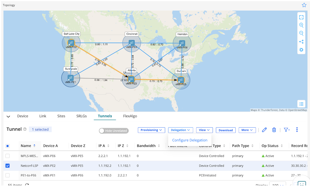
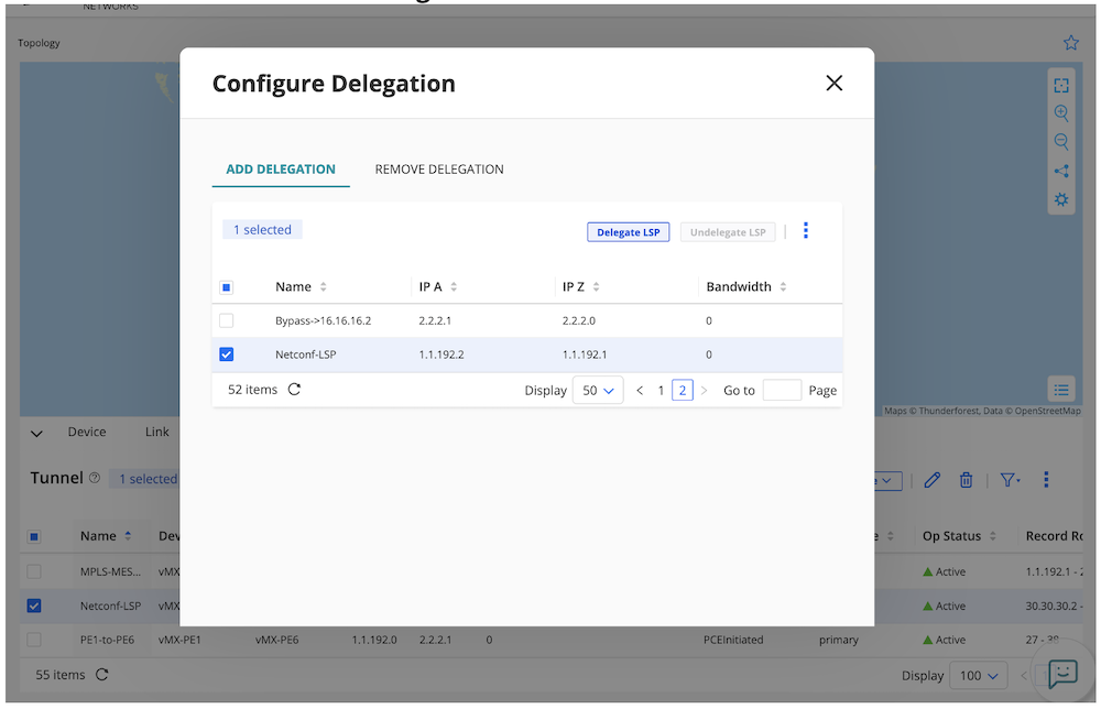
We need to select in the list: Netconf-LSP --> Delegation --> Configure Delegation
Figure 16: LSP Delegation Preparation
Select Netconf-LSP and click on "Delegate LSP"
Figure 17: Final LSP Delegation Step
Once successful, RD GUI will provide the new information for this LSP.
Looks like everything is working perfectly from the router perspective, let's do a quick check in RD, shall we?
Figure 19: Node-SID and Adj-SID Information
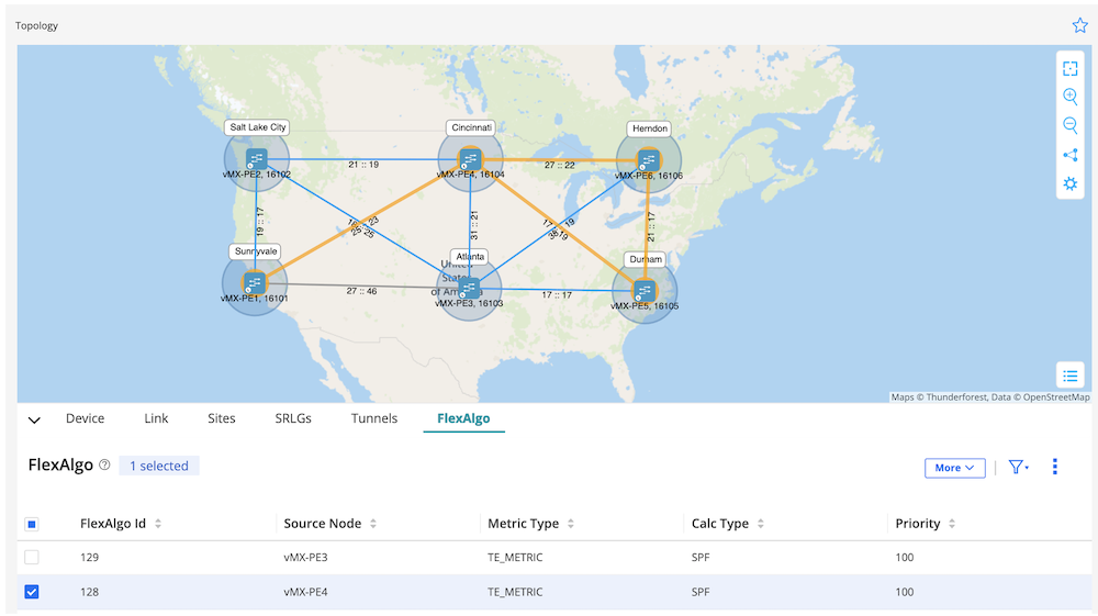
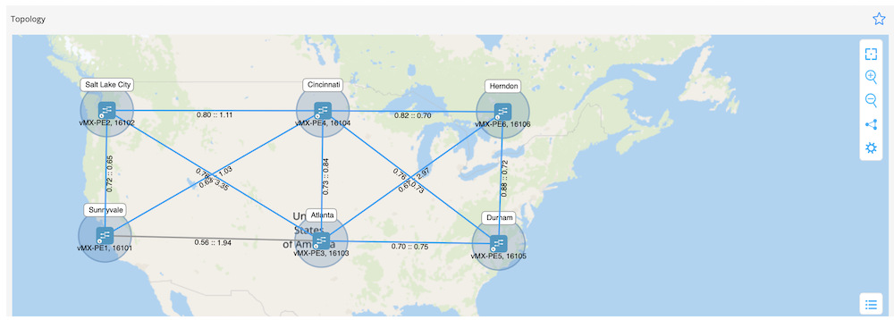
Figure 20: Flex-Algo 128 Topology
Figure 21: Flex-Algo 129 Topology
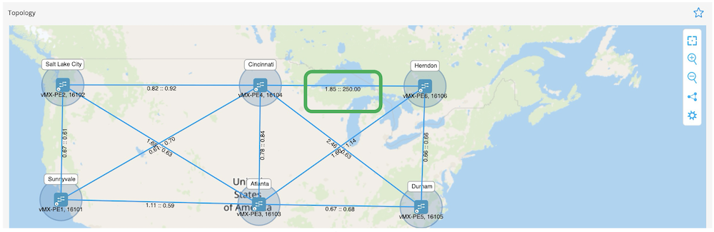
Figure 22: P2P Delay-measurement Information
We can see in Figures 19, 20, 21 and 22 that all SR information (node-SID and Adj-SID), Flex-algo and delay-measurement details are aligned with the routers outputs.
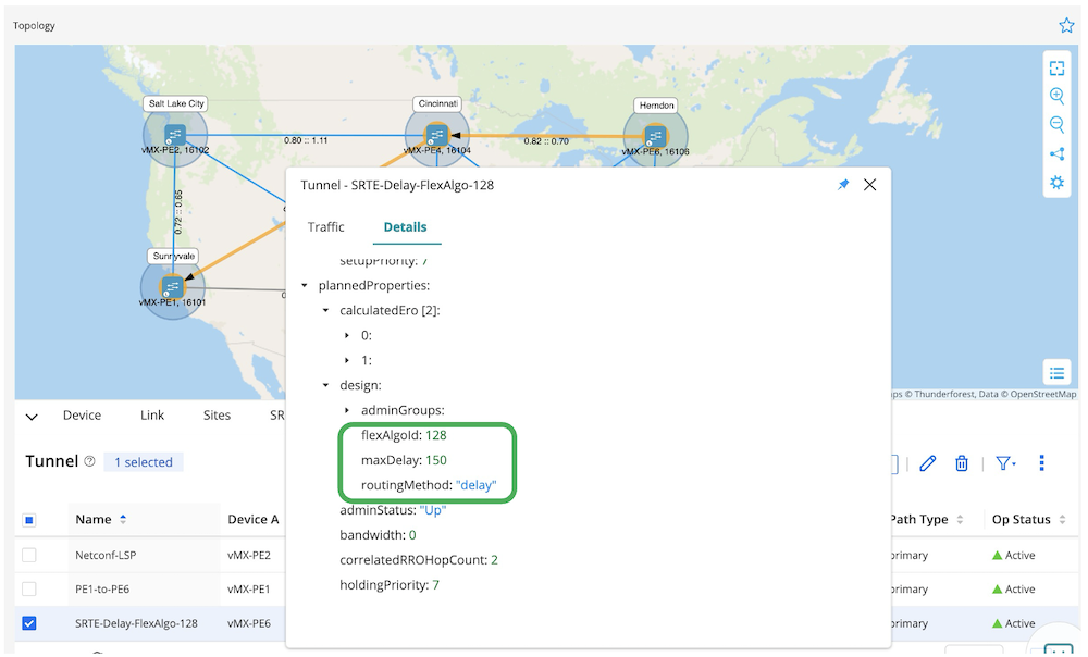
Let's provision our intended SR-TE now. I will create an SR-TE tunnel from PE6 to PE1 for this use case.
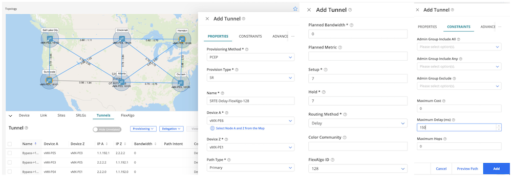
First, we go to Tunnels --> Provisioning and we define important variables in the GUI:
Provisioning Method: PCEP
Provision Type: SR
Name: SRTE-Delay-FlexAlgo-128
Device A: vMX-PE6
Device B: vMX-PE1
Routing Method: Delay
FlexAlgo ID: 128
Constraints Maximum Delay: 150ms
Figure 23: Step-by-step Defining the Variables
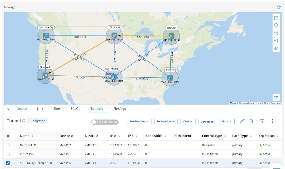
Figure 24: SRTE-Delay-FlexAlgo-128 Tunnel UP
Figure 25: Detail Tunnel Information Align with Defined Variables
After the tunnel has been successfully created, we'll need to exceed the 150ms maximum delay to prove the delay constraint works well. I will statically advertise 250ms delay variation via ISIS IGP protocol for the link PE6 (ge-0/0/2) >< PE4 link (ge-0/0/2) to test this.
jcluser@vMX-PE6# set protocols isis interface ge-0/0/0 delay-metric 250000
jcluser@vMX-PE6# show | compare
[edit groups paragon-service-orchestration protocols isis interface ge-0/0/2.0]
+    delay-metric 250000;
jcluser@vMX-PE6> show ted database extensive | match 250000
      Average delay: 250000
      Minimum delay: 250000
  Average delay: 250000
      Minimum delay: 250000
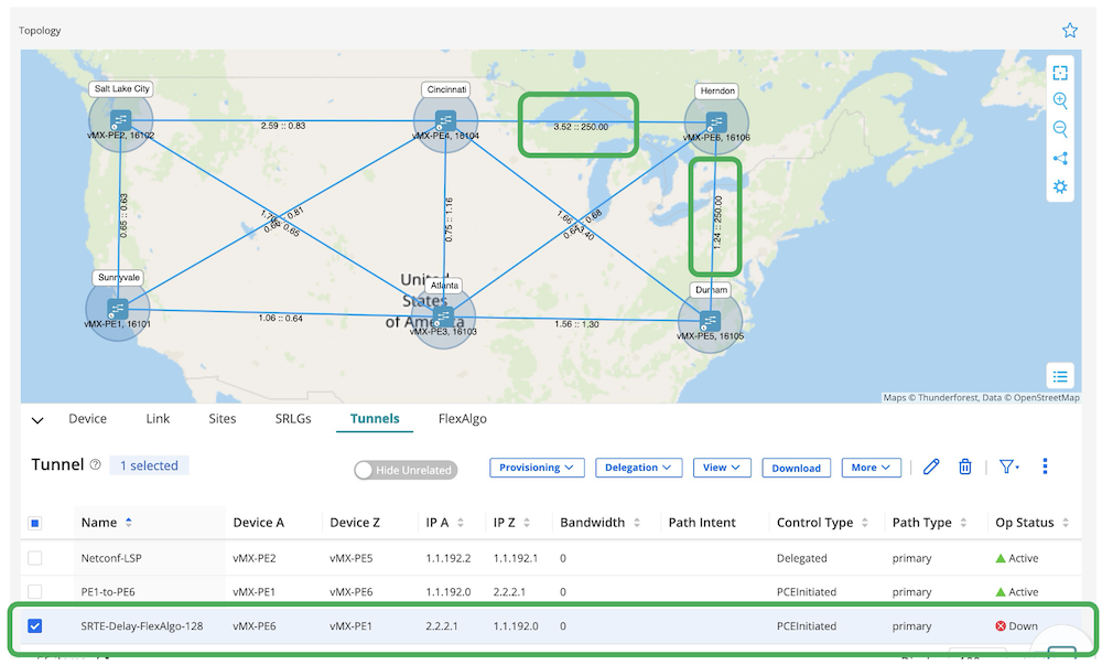
As expected, the tunnel is declared down for two reasons:
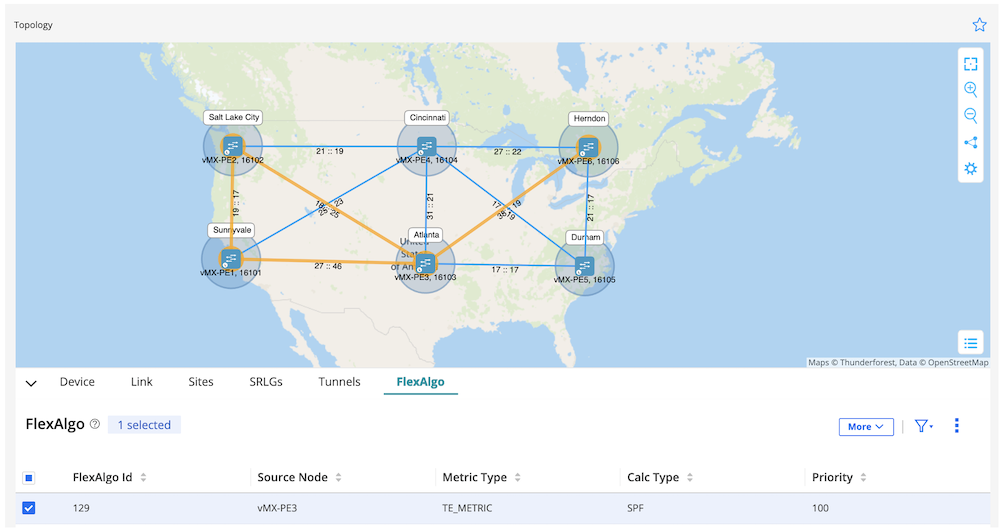
There is no more resource of Flex-algo 128 link in the topology (remember that PE3 is part of Flex-algo 129, hence PE3 >< PE6 link is not part of the Flex-algo 128 resource)
All Flex-algo 128 available links are exceeding the 150ms maximum delay constraint
Figure 28: Delay-measurement and Tunnel Down in RD GUI
This test case proves that RD2.5 can handle multiple constraint tunnels.
Imagine we have hundreds of routers in the network and we need to create a new full mesh LSP traffic engineering. A service provider wants to upgrade the network from MPLS-based LDP/RSVP to SR-MPLS, and SR-TE is mandatory. Configuring routers manually via the CLI will be a tedious and error-prone effort.
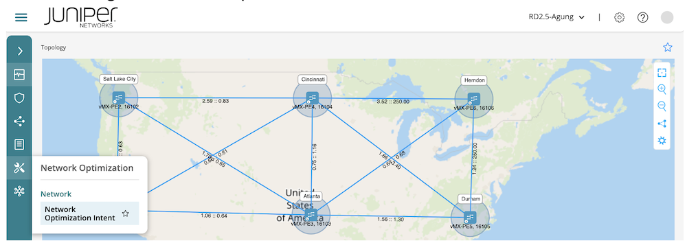
Routing Director introduced a new feature in RD2.5 version to overcome this problem. It's called Network Optimization Intent. **It can automate and create a full mesh LSP with only a few steps. I will show you how easy it is with RD in this last use case.
First, we need to go to the "Network Optimization Intent" tab.
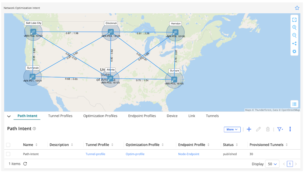
Figure 29: Network Optimization Intent
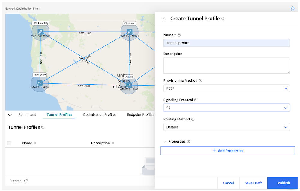
We need to define the "Tunnel Profiles" then click "Publish".
Name: Tunnel-profile
Provisioning Method: PCEP
Signaling Protocol: SR
Figure 30: RD Tunnel Profiles
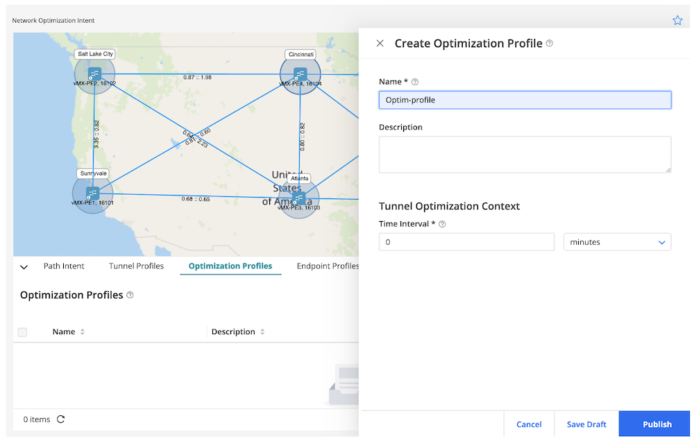
Creating "Optimization Profiles" is the next prerequisite stage, then click "Publish".
Name: Optim-profile
Tunnel Optimization Context: 0 (I will leave it zero, but we can define this as per the requirements)
Figure 31: RD Optimization Profiles
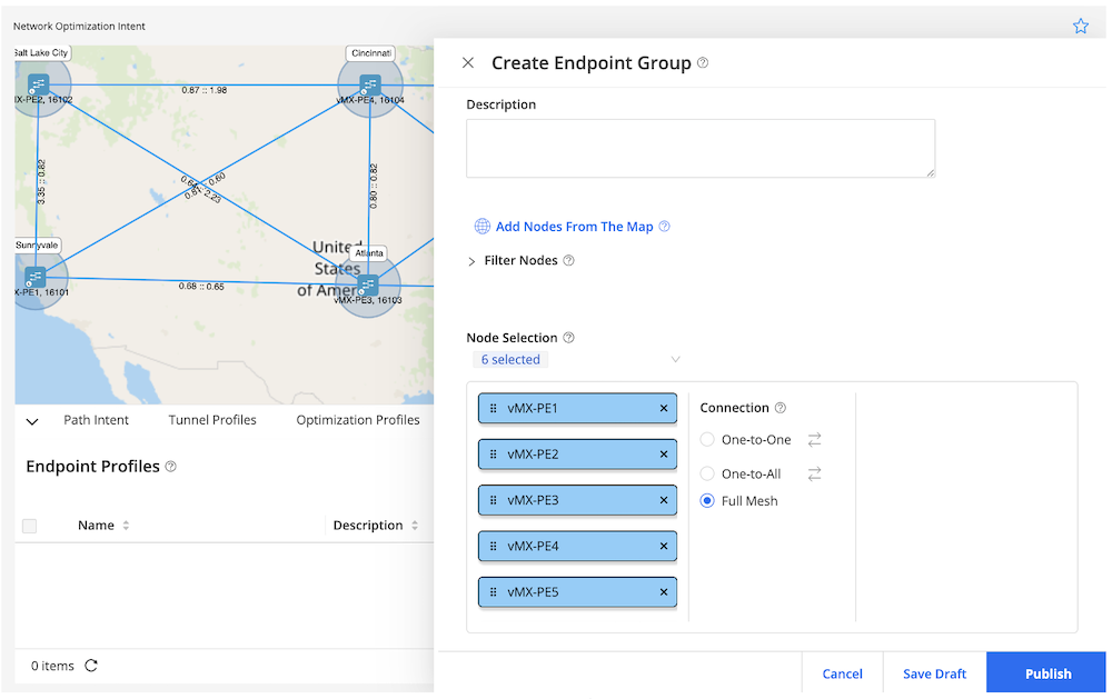
Last one is to define the "Endpoint Group" with the name: Node-Endpoint before we move to the final stage. Then, we click "Publish".
Figure 32: RD Endpoint Group
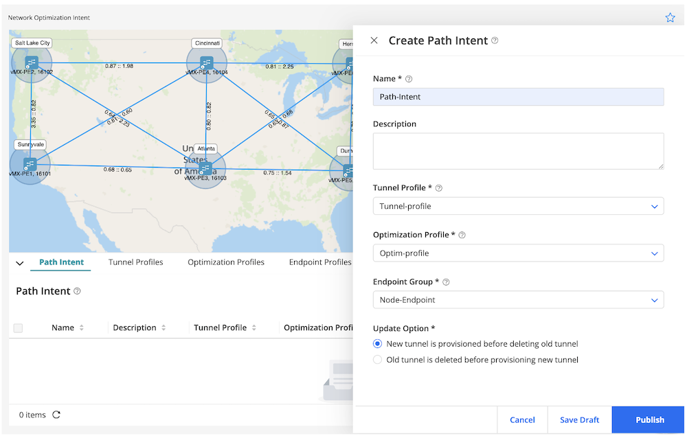
We move to the "Path Intent" after all the prerequisites have been defined as per the capture below and then click "Publish".
Name: Path-Intent
Tunnel Profile: Tunnel-profile
Optimization Profile: Optim-profile
Endpoint Group: Node-Endpoint
Figure 33: RD Path Intent
Since I am creating a full mesh path intent, the total provisioned paths will be using a simple formula Nx(N-1). I have six routers in my lab, hence the total will be 6x(6-1) = 30 provisioned tunnels (with 5 SR-TE tunnels per router) as per Figure 34.
Figure 34: RD Final Result Network Optimization Intent
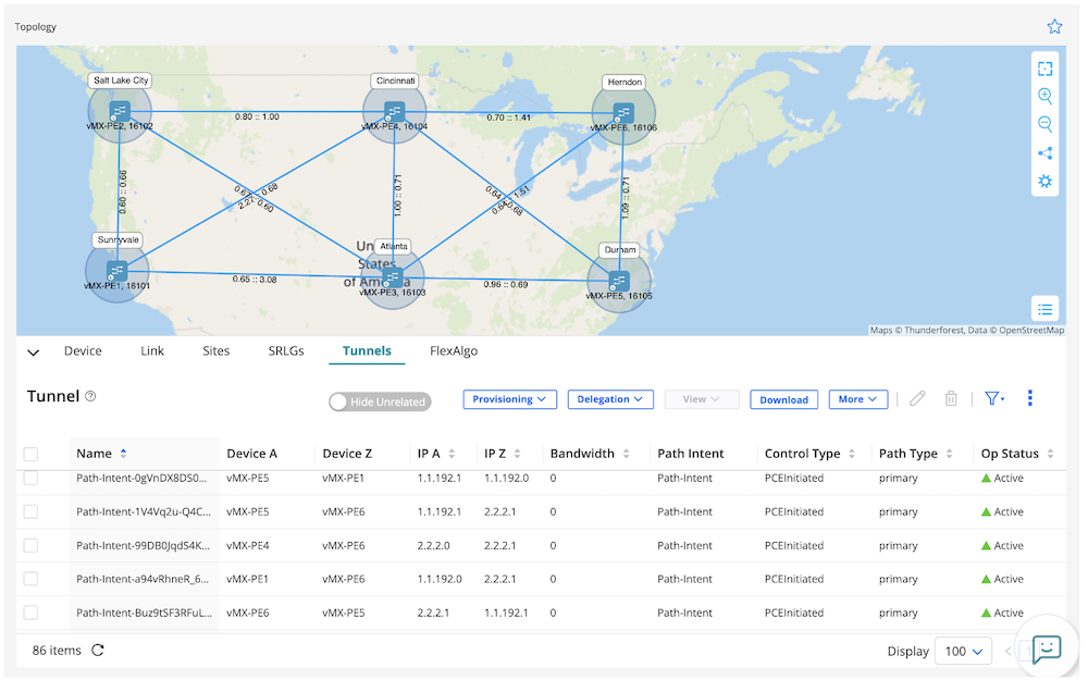
We verify the active tunnels' status in Figure 35
Figure 35: all SR-TE Tunnels Up
I will grab sample output from router PE3 and PE4 for the Network Optimization Intent result.
jcluser@vMX-PE3> show spring-traffic-engineering lsp
To                        State     LSPname
2.2.2.0                   Up        Path-Intent-FG06Dm-8SYe5l08niUlKdg
1.1.192.0                 Up        Path-Intent-Nj9AOi-cRiuOZcdKVA424g
1.1.192.1                 Up        Path-Intent-UUWHi7CRQUiCSfudlW093A
2.2.2.1                   Up        Path-Intent-jYj8-40iSnKKiXWeoFmc0Q
1.1.192.2                 Up        Path-Intent-nBeNfCMATZ6Xg_hhzHkCow

Total displayed LSPs: 5 (Up: 5, Down: 0)

jcluser@vMX-PE4> show spring-traffic-engineering lsp
To                        State     LSPname
2.2.2.1                   Up        Path-Intent-99DB0JqdS4KFuujT0ByUVg
1.1.192.1                 Up        Path-Intent-Dbg3a_SCSCS4Z0FrdJl-fQ
1.1.192.0                 Up        Path-Intent-eUOHnCY_TpO62ik32FMcVw
2.2.2.2                   Up        Path-Intent-pkMy1fDWRbCik4noVLzKmQ
1.1.192.2                 Up        Path-Intent-qm3BZhgdTPaCYEpere2qWw

Total displayed LSPs: 5 (Up: 5, Down: 0)
We can see how easy and fast it is to build full mesh tunnels in the network.
In this Techpost, we described how network automation and optimization can be managed by Routing Director. RD will improve day-to-day operation and ultimately reduce the probability of human error in the network. From creating a new LSP for a specific service with different constraints, delegating LSP from routers to RD, transport network slicing with Flex-algo, to full-mesh tunnel automation provisioning... All were demonstrated and proven in this Techpost article.