PTX10001-36MR L2 Circuit Scale
The PTX10001-36MR is well-known for its core, peering and DCI capabilities, but it's also a very performant L2 aggregation device. In this article, we will test and demonstrate L2 virtual circuits scale on Express4-based PTX routers.
Introduction
Each Express 4 ASIC (Codename: "BT") supports up to 16384 logical interfaces. In this test scenario we distribute logical interfaces between two PFEs of a PTX10001-36MR as shown in Figure 1:
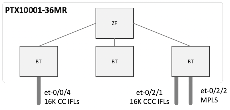
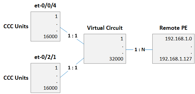
Figure 2 shows relationships between interfaces, circuits and remote edge devices. The setup has a trivial next-hop topology without any load balancing. Note that regular "et-" interfaces are used in this test. With Aggregated Ethernet in use the scale will reduce because, as of today, a separate logical interface is allocated for each member link (also known as "child" IFL).
Configuration and Validation
CCC interface configuration is shown below:
All the circuits are provisioned as static pseudo-wires (32000 total) and 128 static LSPs are provisioned to reach remote PEs.
All the l2 connections are "up" after commit:
PFE commands confirm that 32K MPLS and 32K CCC routes are present.
16K L2 circuits per PFE limit is imposed by the address space of the local L2 domain attribute of the ASIC (14 bits). The mapping of interfaces and VLANs to a logical interface is kept in the L2 domain table.
Utilization of ingress (next-hop) memory is less than 20%.
Egress memory is used for encapsulation structures, such as output VLAN IDs, forwarding MAC addresses and MPLS labels. 4 partitions out of 12 are in use and utilization of these 4 is less than 70%. Overall utilization is less than 30%.
Configuration Generation Script
Glossary
- CCC: Circuit Cross-Connect
- IFL: Logical Interface
- LSP: Label Switched Path
- PE: Provider Edge
- PFE: Packet Forwarding Engine