Securing IPVPN Connectivity on Juniper MX Using Inline IPsec
This article provides an example of using the inline IPsec function available on Trio-6 based MX routers to secure IPVPN traffic over an MPLS core. After stepping through the configuration details of IPsec, verification is performed to validate proper operation and to reinforce the reader's understanding of the implementation.
Introduction
As part of a recent customer POC test, an MX10004 (25.2R1-S1.4) with line card model LC9600 was positioned as a data center gateway router. In the topology diagram below, the MX10004 router, Edge-1, provides interconnectivity between the local EVPN/VXLAN-based multi-tenant data center (DC1) and a remote data center (DC2), reachable via an IP/MPLS core network. This means the MX10004 router adds and removes VXLAN and MPLS headers as needed when forwarding packets. At the remote data center, another MX304 gateway router, Edge-2, provides similar interconnectivity services.
In addition, secure connectivity between the two data centers is established using an IPsec tunnel between the MX gateways. This functionality is enabled by the inline IPsec capability on the Trio 6-based LC9600 and MX304 which provide encryption/decryption without the need of a specialized service card. For more details about inline IPsec on the MX routers see [1].

The goal of the POC test is to extend connectivity for a specific tenant between the data centers. This requires the MX10004 Edge-1 router to exchange EVPN Type 5 IPVPN routes with its BGP peers in DC1, and exchange MPLS-based IPVPN routes with the Edge-2 router at DC2. Once configured, end-to-end connectivity is verified by sending traffic flows between traffic generator ports at each site.
Note that this solution can be adapted for other scenarios as well. For example, the remote site, instead of being another data center, may contain end users that need to access applications or services at DC1.
Configuration
DC1 Fabric
The EVPN/VXLAN fabric in DC1 is managed using Apstra. A Routing Zone, or VRF, named "Tenant-1" is created with VNI "100001" and route target "100001L:1". Then virtual network "V101" is defined and applied to a pair of Leaf devices. The IRB interface of the virtual network is assigned to the "Tenant-1" VRF. Fabric devices exchange EVPN Type 5 routes with the Edge-1 router using BGP.
The details of the Apstra configuration are not shown here for brevity as the focus of this document is on the MX10004 Edge-1 router's IPsec configuration.
DC1 Edge-1 Router
The configuration on the Edge-1 router involves defining the VRF and then creating the secure end-to-end connection to the remote DC. Note that the configuration for Edge-2, although not shown below, is similar.
Because IPVPN is used in the core, packets between the data centers are encapsulated with an MPLS label. This requires the MX to first encapsulate the data with GRE before entering the IPsec tunnel.
As you step through the configuration sections below, please reference the following diagram to better understand and visualize the implementation:
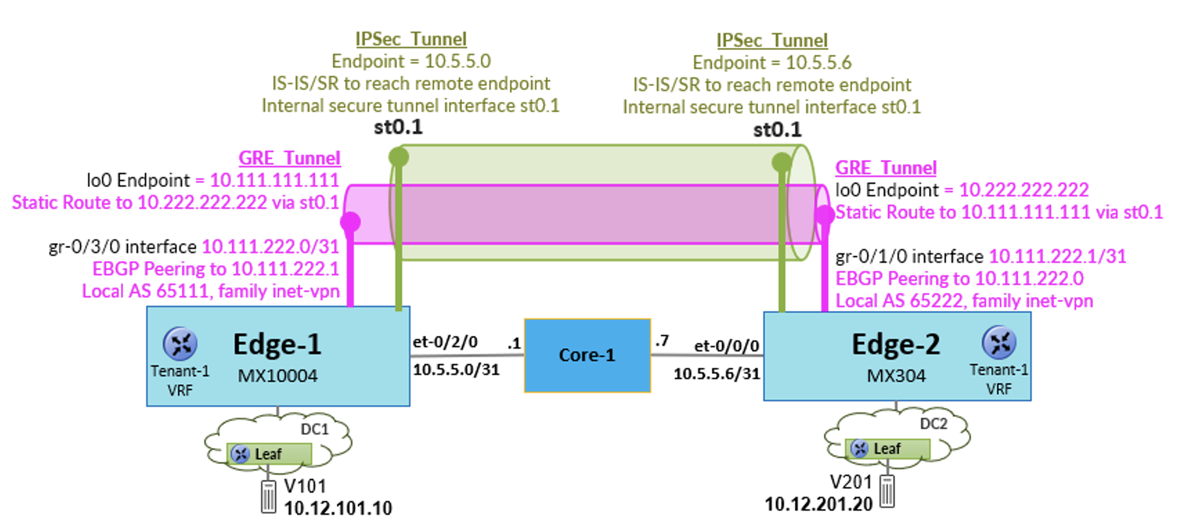
Note that other baseline configuration on the Edge-1 router towards the EVPN/VXLAN fabric (ex. IP underlay, BGP) and IP/MPLS core (ex. IS-IS, MPLS Segment Routing) are omitted for brevity.
VRF
On Edge-1, first configure a VRF instance with 'protocols evpn ip-prefix-routes' so that EVPN Type 5 routes can be exchanged with the DC1 fabric devices. It is also important for the route target to match the value generated by Apstra which is applied on the Leaf devices.
Site to Site Connectivity
IPsec
In this example a Route-Based, or Point-to-Point (P2P), IPsec tunnel is configured. This allows all traffic between the two sites to be encrypted, regardless of source/destination. The MX also supports a Policy-Based, or Traffic Selector (TS), mode where specific traffic flows are permitted through the tunnel based on layer 3 and layer 4 information in the packet header including source/destination address, protocol, and source/destination port. See [2] for more information.
Unified Services
The first step in configuring IPsec on the MX router is to enable Unified Services. Note that it is disabled by default. If the MX router contains multiple routing engines, then Unified Services must be explicitly enabled on each one. A reboot is required after enabling.
Once the MX is up and running again, verify the status with the following command.:
Interfaces
Before adding the IPSec related configuration. It is important to understand the new types of interfaces. An overview is provided here. Again, please reference the previous Tech Post [1] for more details.
- Service Interface - this interface is denoted as "si-". It is a virtual interface that resides on the PFE and provides encryption/decryption services.
The Service Interface consists of an 'inside' interface and an 'outside' interface which are defined as IFLs. For example, if resources from a line card in slot 0 pic 3 are allocated to the service interface, the 'inside' interface can be configured as 'si-0/3/0.0' and the 'outside' interface as 'si-0/3/0.1'. The inside interface receives unencrypted traffic and forwards it to the crypto block in the PFE. The encrypted traffic is sent out the outside interface and then routed to the appropriate egress port. The outside interface receives encrypted traffic and forwards it to the crypto block in the PFE for decryption The traffic is then forwarded to the appropriate egress port. The service interface can provide encryption/decryption services to multiple secure tunnel interfaces. - Secure Tunnel Interface - this interface is denoted as 'st0'. It is an internal interface that routes traffic to/from the IPsec VPN Tunnel. There is one 'st0' IFL per IPsec tunnel, for example 'st0.1'.
Service Interface
On the Edge-1 router, determine which PFE to use for the service interface. In this example, the LC9600 line card is in slot 0 and resources are allocated from the PFE associated with PIC 3.
Note that its strongly recommended to explicitly set the 'service-port' and 'bandwidth' for efficient allocation of the PFE resources. In this case only a single service interface is required, and therefore a single service port (i.e. 'service-port 0') is specifically configured.
Then define the inside and outside service interfaces and include them in a Service Set. In a future step (see below), the IPsec tunnel will be configured and assigned to this Service Set for crypto services.
IKE
Next, define the IKE gateway. The authentication method uses pre-shared keys which must match at both endpoints. When defining the gateway, the IP address assigned to Edge-1's core facing interface (i.e. et-0/2/0) is specified as the local address. Similarly, the target address is the IP address of Edge-2's core interface.
IPsec
On Edge-1, first define a secure tunnel interface to be associated with IPsec tunnel (ex. st0.1). Then define the IPsec proposal and policy as shown below.
When defining the IPsec VPN, specify the secure tunnel interface and reference the previously configured IKE gateway.
Finally, associate the IPsec VPN with the previously configured Service Set which determines which PFE will provide encryption/decryption services for the tunnel.
GRE
As mentioned above, GRE is required for this solution on the MX router because the routed traffic in the tunnel is encapsulated with an MPLS label. In this example, the GRE interface, 'gr-0/3/0', uses the same ASIC (i.e. slot 0 pic 3) as the IPsec service interface for GRE encapsulation/decapsulation services.
The GRE Tunnel endpoint is a loopback address on the Edge-1 router. An IP address for point-to-point connectivity with the tunnel is defined on the GRE interface using the 10.111.222/31 subnet. In addition, it is important to enable 'family mpls' on the GRE tunnel interface as labeled packets will be transmitted and received.
The path to reach the remote GRE tunnel endpoint is via the IPsec secure tunnel interface (st0.1) using the configured static route.
BGP
Finally, create a BGP session which runs inside the GRE tunnel between the 'gr-' tunnel interfaces at each site.
Verification
Control Plane
View the IKE and IPSec security associations on the Edge-1 router. More details can be viewed with the 'detail' keyword, however, for now we just want to verify that the security associations are "UP' and active:
Verify that the GRE interface is "Up":
Verify that the BGP session to the remote gateway's GRE interface is established and the route prefix corresponding to V201 at DC2 is received:
View the Tenant-1 route table and confirm that it contains routes corresponding to the host subnets in the two data centers. The subnet in DC1 is learned via EVPN from two different VTEPs (i.e. due to ESI LAG, not shown in the topology diagram) which are reachable via 4 different underlay links.
The remote subnet in DC2, '10.12.201.0/24', is learned via the BGP IPVPN prefix advertisement. Note that the next-hop to DC2 is via the GRE tunnel interface and that an MPLS label is added to the forwarded packets.
Data Plane
Each host in the topology is emulated using a traffic generator tester port. Packets, random size 128B to 9000B, are transmitted bi-directionally at a rate of 1000 pps.
View the traffic generator statistics to confirm bi-directional connectivity:

Stop the traffic flows.
Now send only the flow from DC1 to DC2 at a rate of 1000 pps. Then view the interface statistics on Edge-1.
The MX10004 Edge-1 router receives 1000 pps from the fabric on interface et-0/2/3. These packets are forwarded via the GRE gr-0/3/0 interface (1000 pps) to the IPsec secure tunnel interface. The traffic is then passed through the service interface's 'inside' and 'outside' sub-interfaces (2000 pps) for encryption and then forwarded out the et-0/2/0 egress port towards Core (1000 pps).
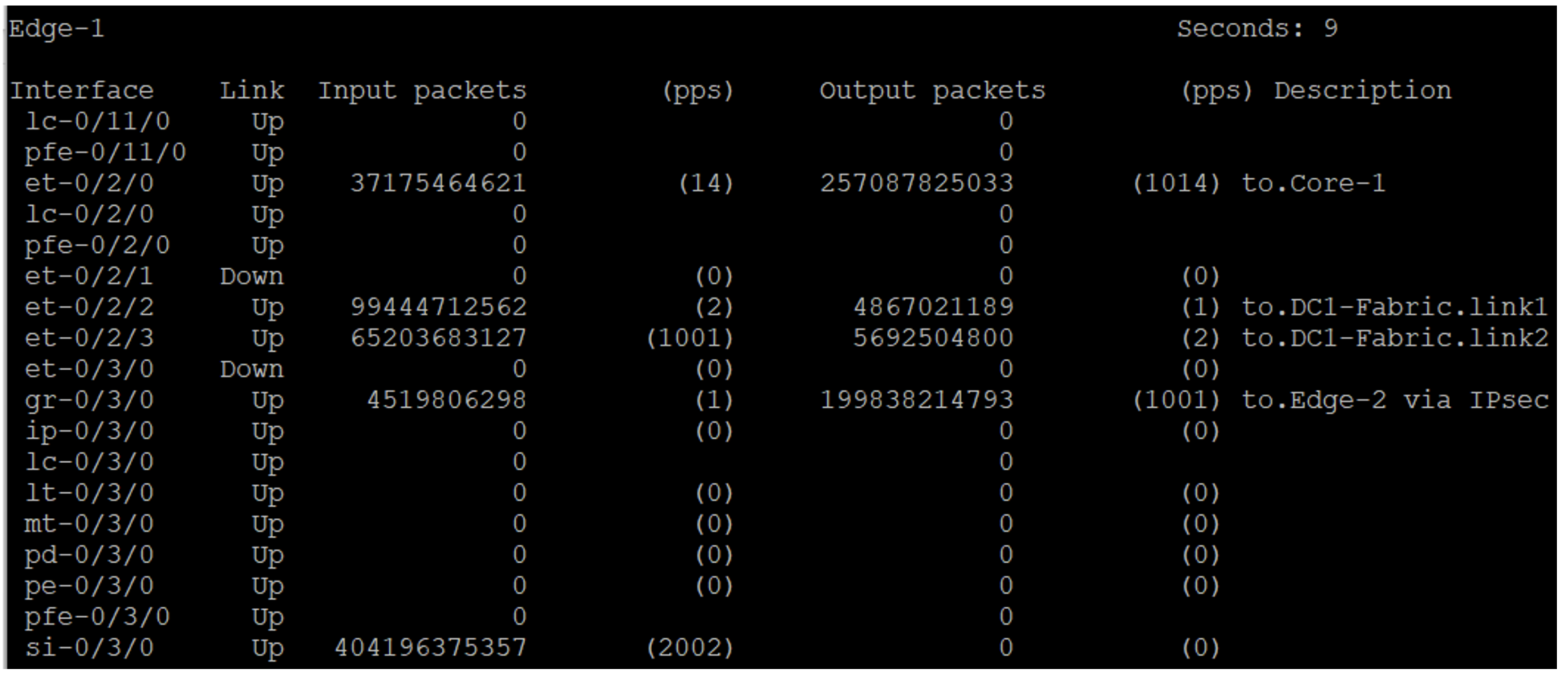
For a different perspective, view the secure tunnel and service interface statistics. The secure tunnel interface is forwarding traffic (1000 pps) to the 'inside' service interface for encryption. The traffic is then passed to the 'outside' service interface (1000 pps) before being routed towards the core. As mentioned above, for encryption, traffic passes through both the inside and outside service interfaces. Note that the 'input' and 'output' counters reflect the MX's internal forwarding path.
Stop the traffic flow. Now send only the flow from DC2 to DC1 and view the statistics on Edge-1 again.
The flow is received from the Core router on interface et-0/2/0 (1000 pps) then decrypted by the si-0/3/0 service interface (1000 pps). Remember, for decryption, traffic only passes through the outside interface.
Via the secure tunnel interface, the traffic is then passed to GRE interface gr-0/3/0 (1000 pps) and then routed towards the DC1 fabric facing port et-0/2/3.
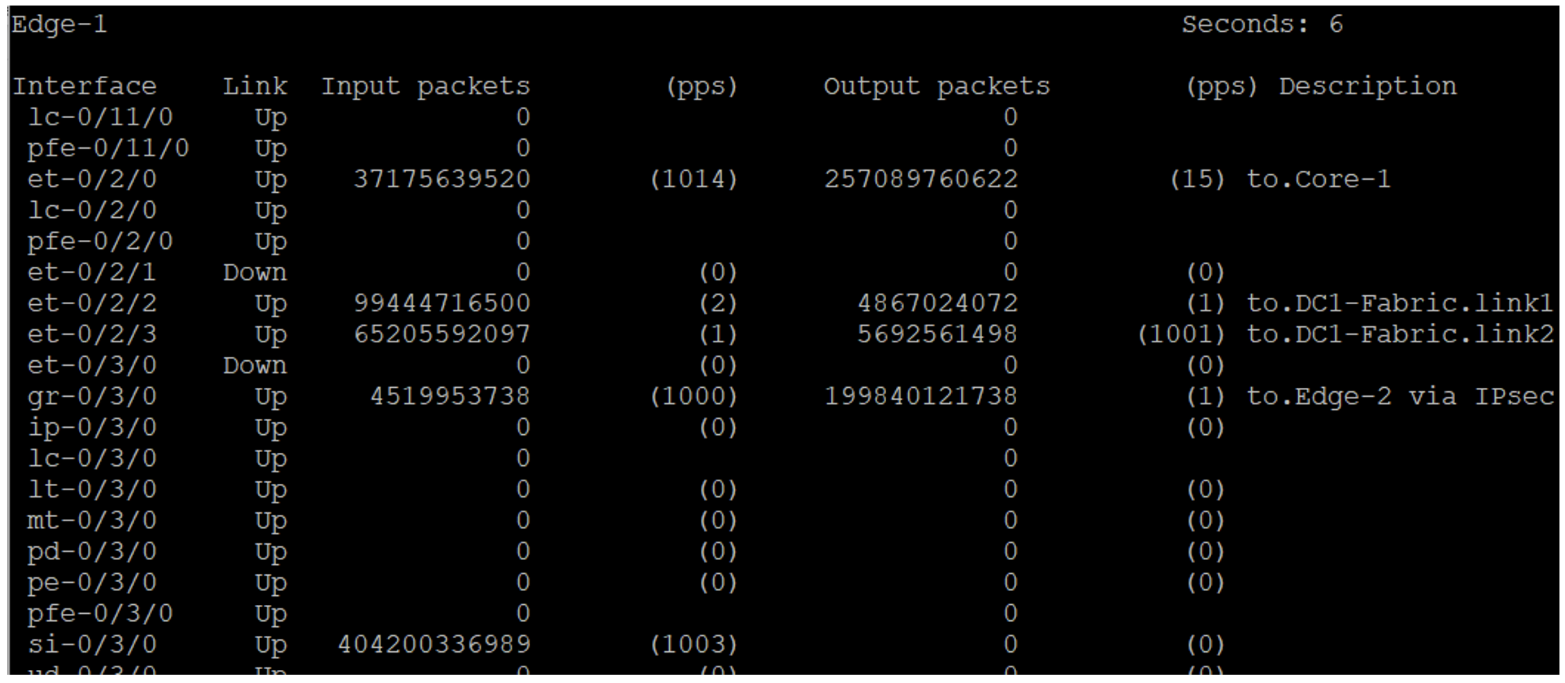
Again, view secure tunnel and service interface statistics. The secure tunnel interface is receiving 1000 pps from the 'outside' service interface. Note that only the 'outside' service interface processes packets in this scenario.
Useful Links
- [1] Inline IPsec - HPE Juniper Networking TechPost blog - https://juniper.github.io/techposts/inline-ipsec-on-mx-series/article
- [2] IPsec VPN Overview - HPE Juniper Network Technical Publication - https://www.juniper.net/documentation/us/en/software/junos/vpn-ipsec/topics/topic-map/security-ipsecvpn-overview.html
- [3] SRX4700 100Gbps Full Duplex IPSEC tunnel - https://juniper.github.io/techposts/srx4700-100gbps-full-duplex-ipsec-tunnel/article
Glossary
- AES: Advanced Encryption Standard
- ASIC: Application-Specific Integrated Circuit
- AS: Autonomous System
- BFD: Bidirectional Forwarding Detection
- BGP: Border Gateway Protocol
- DC: Data Center
- ESP: Encapsulating Security Payload
- ESI: Ethernet Segment Identifier
- EVPN: Ethernet VPN
- GRE: Generic Routing Encapsulation
- IFL: Interface Logical
- IKE: Internet Key Exchange
- IP: Internet Protocol
- IPsec: Internet Protocol Security
- IPVPN: IP Virtual Private Network
- IRB: Integrated Routing and Bridging
- IS-IS: Intermediate System to Intermediate System
- LAG: Link Aggregation Group
- LC: Line Card
- MPLS: Multiprotocol Label Switching
- MTU: Maximum Transmission Unit
- P2P: Point-to-Point
- PFE: Packet Forwarding Engine
- PIC: Physical Interface Card
- POC: Proof of Concept
- PPS: Packets Per Second
- TS: Traffic Selector
- VNI: VXLAN Network Identifier
- VPN: Virtual Private Network
- VRF: Virtual Routing and Forwarding
- VXLAN: Virtual Extensible LAN
Acknowledgments
Special thanks to my colleagues listed below for their assistance with the configuration and taking the time to review this article:
- Poorna-Pushakal Balasubramanian
- Vimalkumar Patel
- Matthijs Nagel
- Karel Hendrych