Manual service provisioning in the network is tedious and cumbersome. Operators have to stitch multiple workflows to complete a service order. For example, identify network resources (ports, bandwidth, VLAN, ... etc.) to fulfill the business intent, provision of VPN services into the devices, verify the connectivity and measure SLA before handover to the end-user, and so on. Each workflow might involve different tools. This creates development and maintenance overhead to stitch the workflows. This is even more challenging in multi-vendor networks in which the operators need to apply different vendor devices' configurations and CLIs. The process is usually time-consuming, prone to human error, and hard to scale.
To tackle the above problems, Juniper Networks provides Paragon Automation (PA) solution which offers automated and intent-based service orchestration capability on a single pane of glass. Operators can seamlessly design the service order, check if the network has sufficient resources to fulfill the intent, provision service to multi-vendor devices, assure SLA, and keep monitoring the performance.
We have described intent-based service orchestration and its efficiency in various articles [1][2]. In this TechPost, we will showcase Paragon Automation's capability of the use case and detail the major steps of the orchestration workflow.
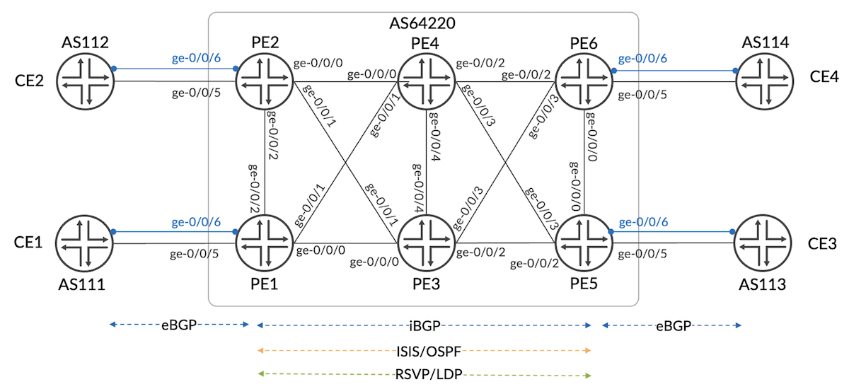
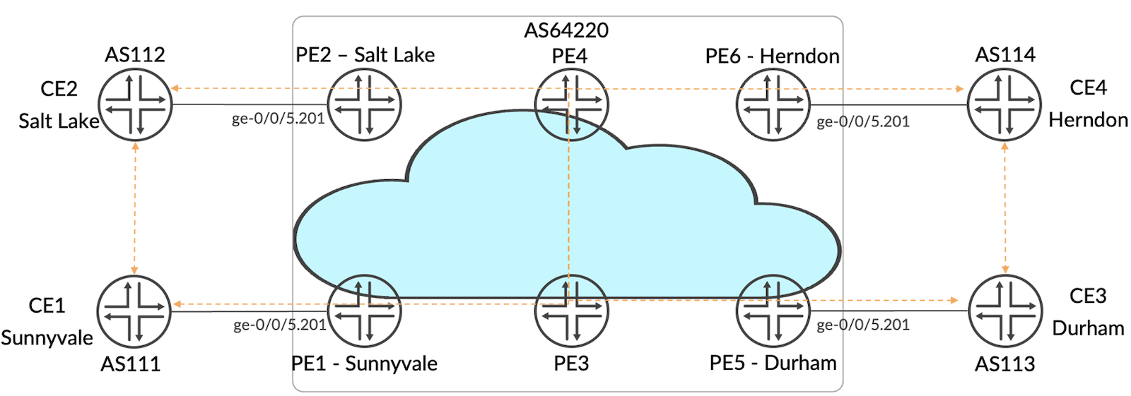
Figure 1 shows the network topology used to demonstrate service orchestration by Paragon Automation. PE1 to PE6 are onboarded and managed by Paragon. Each PE is assigned to a site and location as follow:
PE1: Sunnyvale
PE2: Salt Lake City
PE3: Atlanta
PE4: Cincinnati
PE5: Durham
PE6: Herndon
CEs are customer premises devices used to verify end-to-end connectivity. They are not under management by Paragon Automation.
Figure 1: Network Topology
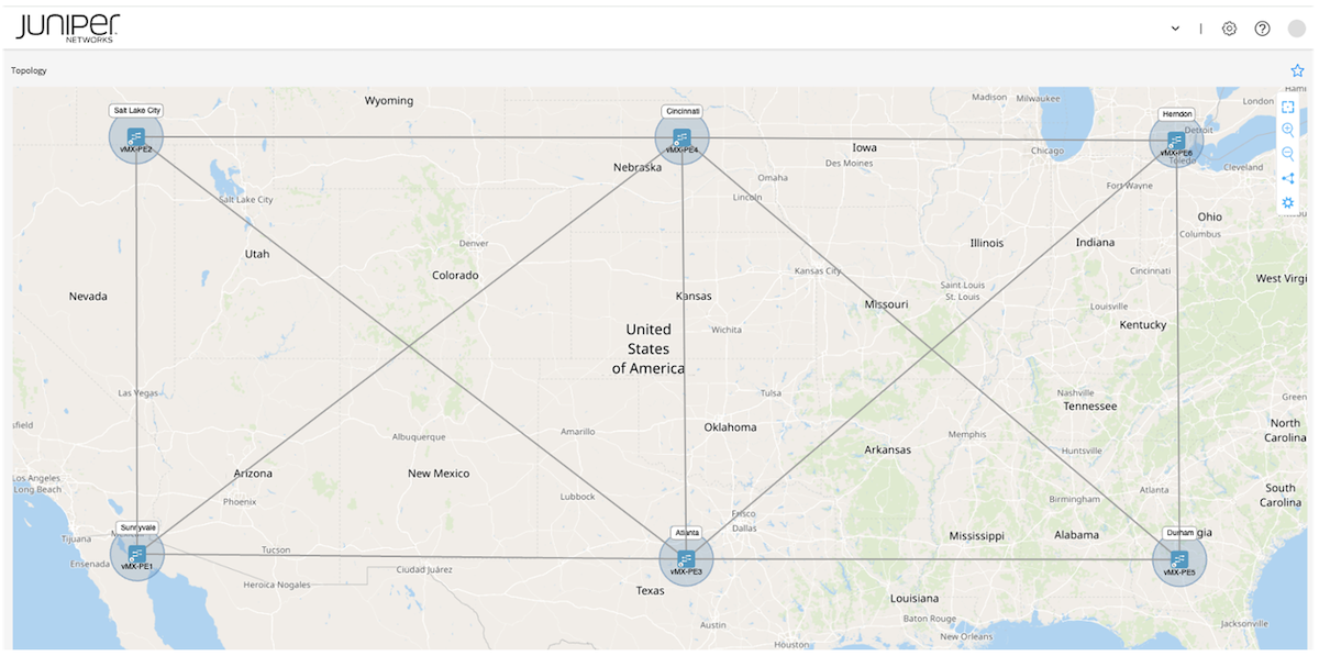
Paragon Automation offers real-time topology discovery by BGP-LS. When the devices are connected by IGP, the topology can be visualized on the GUI depicted in Figure 2. Paragon Automation 2.2 (Figure 3) and Junos 23.4R1.9 are used in this demonstration.
jcluser@vMX-PE1> show version
Hostname: vMX-PE1
Model: vmx
Junos: 23.4R1.9
JUNOS OS Kernel 64-bit  [20231122.ee0e992_builder_stable_12_234]
JUNOS OS libs [20231122.ee0e992_builder_stable_12_234]
JUNOS OS runtime [20231122.ee0e992_builder_stable_12_234]
... Truncated ...
Service orchestration is the workflow of designing, configuring, validating, and monitoring a network service. It manages the entire life cycle of a network service including creation, modification, and decommissioning.
On Paragon Automation, the following procedures are attached to the orchestration workflow.
Create VPN resource components
Design service order (business intent)
Publish service order
Orchestrate Active Assurance workflow to measure and keep monitoring the SLA
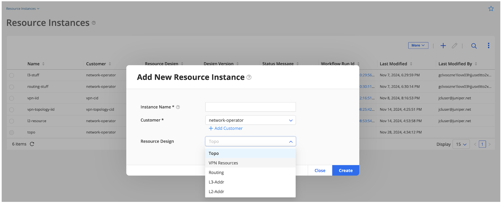
VPN resources are network physical or virtual resources that are available for service order fulfillment. The following VPN resources can be created on GUI (Figure 4) or API.
Topology (topo) resource: CE-facing physical or logical interfaces, their speed, and VLAN ID on VPN-capable PEs
VPN (vpn) resource: route distinguisher, route target, community (l2circuit), and VC ID (l2circuit)
L3 address (l3-addr) resource: L3VPN CE-facing IP addresses
L2 address (l2-addr) resource: EVPN ESI address, LACP admin key and system-id
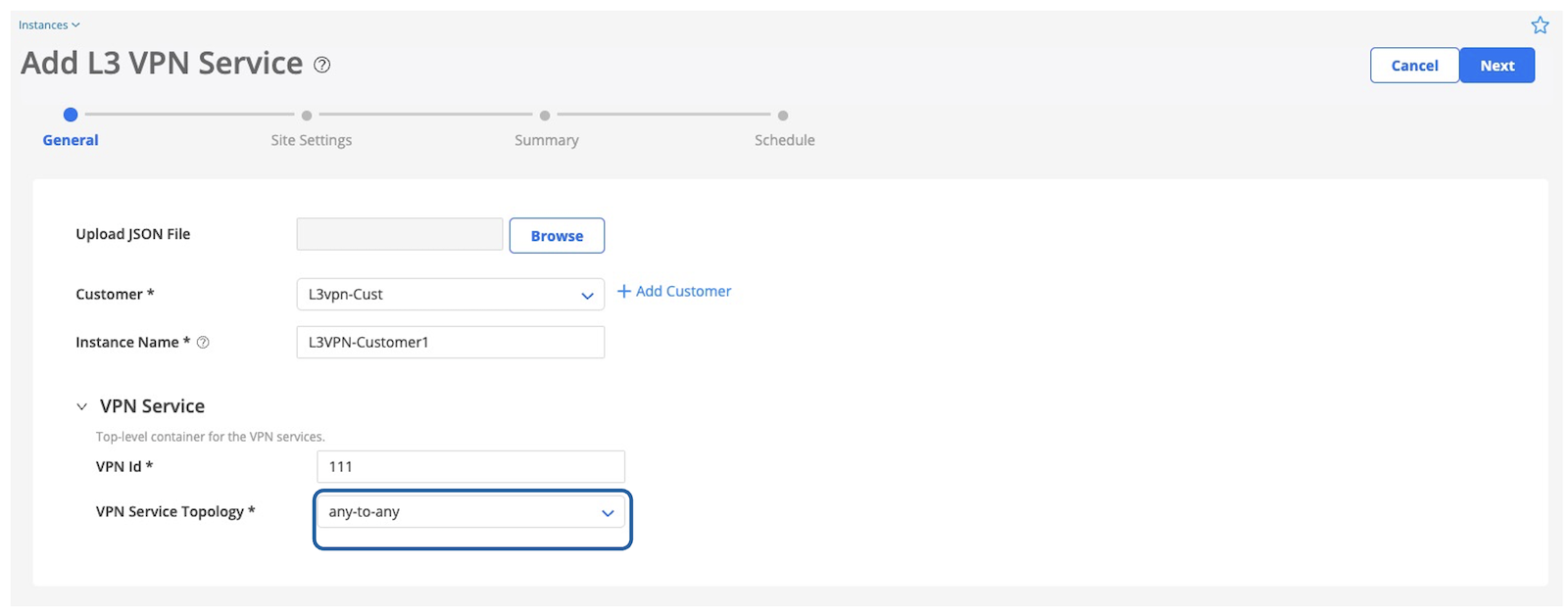
Let's start to design an L3VPN service. PA supports any-to-any and hub-and-spoke L3VPN service orchestration. In this example, any-to-any service is demonstrated.
Below is the business intent of this L3VPN service:
VPN topology: Any-to-any
Service will be terminated in Sunnyvale, Salt Lake, Herndon and Durham
CE-facing interface is ge-0/0/5 on all PEs
VLAN ID: 201
Bandwidth requirement: 1Gbps
Figure 5: L3VPN Any-to-any topology
1.1. Create Service Order
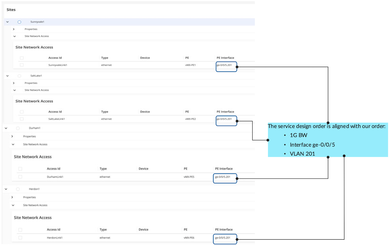
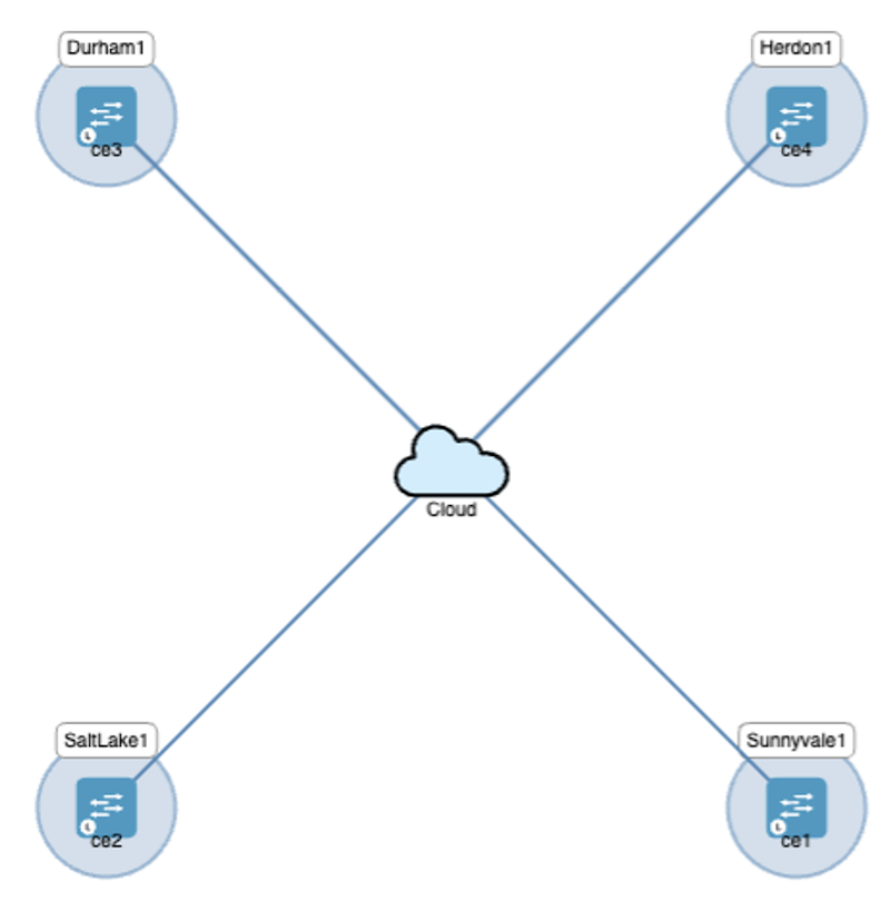
Service order that fulfills the intent is created on GUI by manual input or upload JSON form. Alternatively, this can be created via API. The following figure shows the service order created on GUI. The L3VPN consists of 4 sites with ge-0/0/5.201 as CE-facing interface. VPN topology can also be previewed before order publishment.
Figure 6: L3VPN Any-to-any Service Topology
Figure 7: Site and Interface Parameters
Figure 8: Service Topology of L3VPN (Any-to-any)
1.2. Publish Service Order
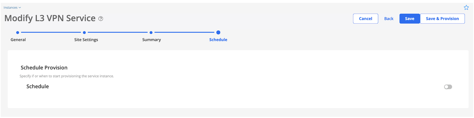
Then we hit "Save & Provision" to publish the service order.
Figure 9: Hit "Save & Provision" to publish the L3VPN service order
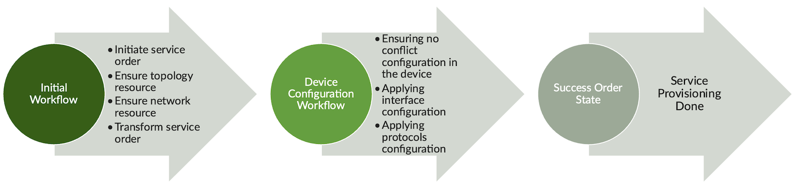
When the order is submitted, the orchestration engine will trigger the following workflow depicted in Figure 10.
First, Paragon checks the availability of the required resource. For example, if VLAN ID 201 is used by another VPN, the check will fail, and Paragon will return an error message. Upon the resources are assured, the service order will be transformed into device configuration and applied to the devices by NETCONF/YANG.
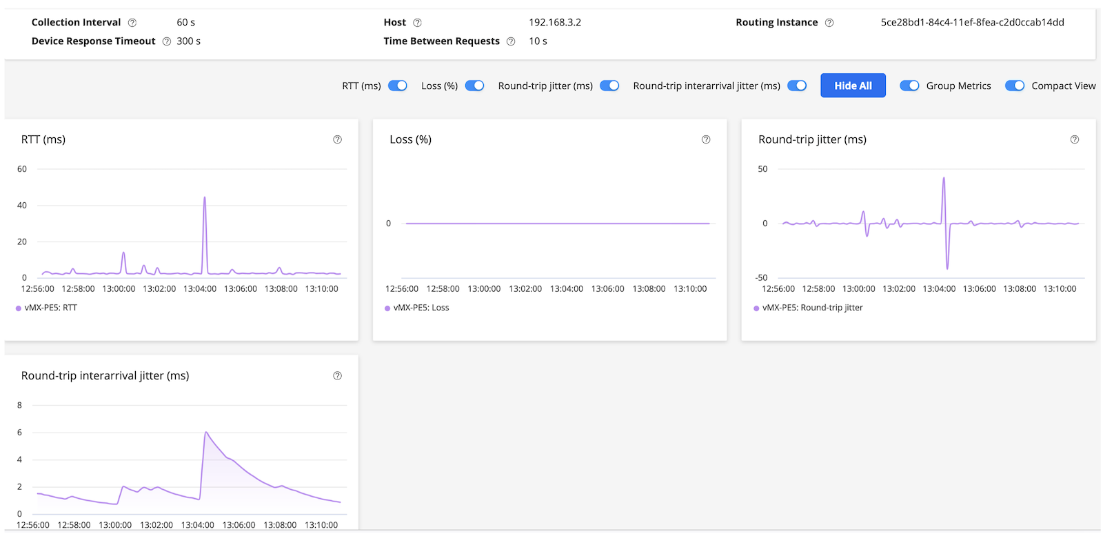
When the configuration is successfully committed, the orchestration engine will trigger SLA measurement (section 1.4). In this demonstration, fully-mesh RPM is set up to measure delay, jitter, and packet loss among participated PEs and CEs. The workflow also creates a monitoring dashboard on GUI such that the operator can inspect the SLA and easily identify any anomaly in the VPN service.
Figure 10: L3VPN High-Level Service Orchestration Workflow
The service order status becomes "success" when the workflow is completed.
Figure 11: Success L3VPN Service Provisioning Order State in PA GUI
1.3. L3VPN Service Provisioning Verification in Routers
PA will transform the service order into device config and push them to the router as part of the service orchestration workflow. Now, let's verify the L3VPN configuration that has been provisioned in the routers. For simplicity, we use PE1 and PE2 to verify the L3VPN service.
jcluser@vMX-PE1> show route table ec420f5e-b2d9-11ef-b5e5-5a21a950e2af.inet.0

ec420f5e-b2d9-11ef-b5e5-5a21a950e2af.inet.0: 5 destinations, 5 routes (5 active, 0 holddown, 0 hidden)
+ = Active Route, - = Last Active, * = Both

192.168.1.0/24     *[Direct/0] 23:56:17
                    >  via ge-0/0/5.201
192.168.1.2/32     *[Local/0] 23:56:17
                       Local via ge-0/0/5.201
192.168.2.0/24     *[BGP/170] 23:56:14, localpref 100, from 1.1.192.0
                      AS path: I, validation-state: unverified
                    >  to 26.26.26.2 via ge-0/0/1.0, label-switched-path MPLS-MESH-from-vMX-PE1-to-vMX-PE2
                       to 18.18.18.2 via ge-0/0/2.0, label-switched-path Bypass->26.26.26.2
192.168.3.0/24     *[BGP/170] 10:22:56, localpref 100, from 2.2.2.0
                      AS path: I, validation-state: unverified
                    >  to 33.33.33.2 via ge-0/0/0.0, label-switched-path MPLS-MESH-from-vMX-PE1-to-vMX-PE5
                       to 26.26.26.2 via ge-0/0/1.0, label-switched-path Bypass->33.33.33.2
192.168.4.0/24     *[BGP/170] 23:56:17, localpref 100, from 1.1.192.2
                      AS path: I, validation-state: unverified
                    >  to 26.26.26.2 via ge-0/0/1.0, label-switched-path MPLS-MESH-from-vMX-PE1-to-vMX-PE6
                       to 18.18.18.2 via ge-0/0/2.0, label-switched-path Bypass->26.26.26.2

jcluser@vMX-PE2> show route table ec420f5e-b2d9-11ef-b5e5-5a21a950e2af.inet.0

ec420f5e-b2d9-11ef-b5e5-5a21a950e2af.inet.0: 5 destinations, 5 routes (5 active, 0 holddown, 0 hidden)
+ = Active Route, - = Last Active, * = Both

192.168.1.0/24     *[BGP/170] 1d 00:42:42, localpref 100, from 3.3.3.1
                      AS path: I, validation-state: unverified
                    >  to 18.18.18.1 via ge-0/0/2.0, label-switched-path MPLS-MESH-from-vMX-PE2-to-vMX-PE1
                       to 21.21.21.1 via ge-0/0/0.0, label-switched-path Bypass->18.18.18.1
192.168.2.0/24     *[Direct/0] 1d 00:42:43
                    >  via ge-0/0/5.201
192.168.2.2/32     *[Local/0] 1d 00:42:43
                       Local via ge-0/0/5.201
192.168.3.0/24     *[BGP/170] 11:09:27, localpref 100, from 2.2.2.0
                      AS path: I, validation-state: unverified
                    >  to 28.28.28.1 via ge-0/0/1.0, label-switched-path MPLS-MESH-from-vMX-PE2-to-vMX-PE5
                       to 21.21.21.1 via ge-0/0/0.0, label-switched-path Bypass->28.28.28.1
192.168.4.0/24     *[BGP/170] 16:14:14, localpref 100, from 1.1.192.2
                      AS path: I, validation-state: unverified
                    >  to 18.18.18.1 via ge-0/0/2.0, label-switched-path MPLS-MESH-from-vMX-PE2-to-vMX-PE6
                       to 21.21.21.1 via ge-0/0/0.0, label-switched-path Bypass->18.18.18.1
1.4. Orchestrate with Active Assurance for SLA Measurement
After L3VPN is successfully provisioned into the devices, PA can orchestrate with the active assurance workflow to affirm connectivity is up and keep monitoring the SLA throughout the lifecycle until the service is decommissioned. This ensures the SLA is fulfilled before the service is handover to the end-user and keeps performing well.
In this example, the orchestration engine provisions real-time performance monitoring (RPM) to VPN PEs as part of the active assurance workflow. This creates fully-mesh RPM test session between PEs and CEs. KPIs such as end-to-end round trip delay, jitter, and packet loss are reported and visualized on Paragon's observability dashboard.
The following config sample shows RPM sessions initiated from PE1 to remote PEs' CE-facing interfaces and CE devices.
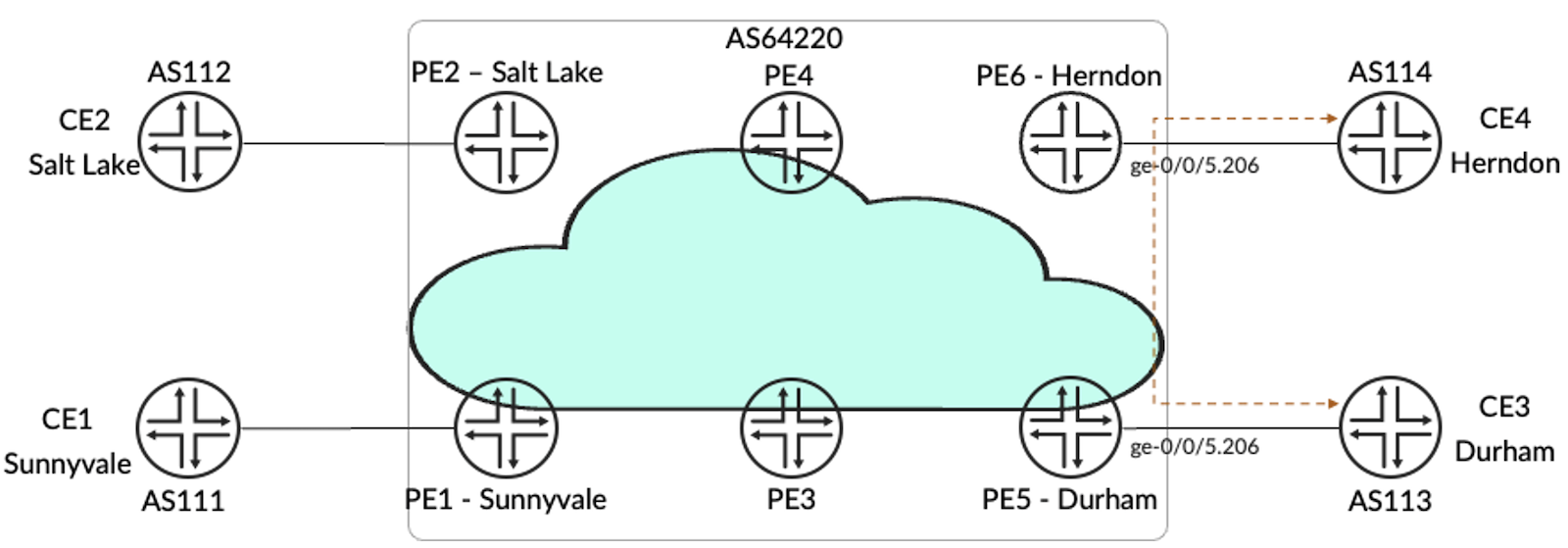
Next, we will demonstrate EVPN service orchestration. PA supports both single-homed and dual-homed EVPN. In this example, the former is demonstrated with the following business intent.
Single-homed
Service will be terminated on Durham and Herndon
CE-facing interface from PE is ge-0/0/5
VLAN ID: 206
Bandwidth requirement: 1Gbps
Figure 13: EVPN Topology
2.1. Create Service Order
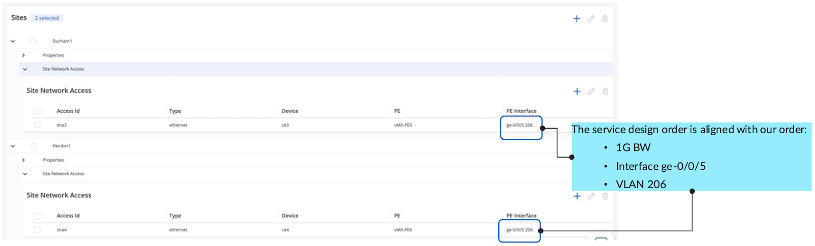
Figure 13 shows the service order created on GUI. The EVPN consists of 2 sites with ge-0/0/5.206 as CE-facing interface. VPN topology can also be previewed and confirmed before order publishment.
Figure 14: Site and Interface Parameters
Figure 15: Service Topology in PA GUI
2.2. Publish Service Order
Then, we hit "Save & Provision" to publish the service order.
Figure 16: Hit "Save & Provision" to publish the EVPN service order
The following workflow will be triggered
Figure 17: EVPN and L2Circuit Workflow
Figure 18: The service order status becomes "success" when the EVPN workflow is completed.
2.3. EVPN Service Provisioning Verification in Routers
PA will transform the service order into device config and push them to the routers as part of the service orchestration workflow.
jcluser@vMX-PE5> show route table 3e8931aa-a00e-11ef-b5c3-deba06bc9197.evpn.0

3e8931aa-a00e-11ef-b5c3-deba06bc9197.evpn.0: 2 destinations, 2 routes (2 active, 0 holddown, 0 hidden)
+ = Active Route, - = Last Active, * = Both

3:1234:2::0::2.2.2.0/248 IM
                   *[EVPN/170] 10:26:53
                       Indirect
3:1234:3::0::1.1.192.2/248 IM
                   *[BGP/170] 10:26:50, localpref 100, from 1.1.192.2
                      AS path: I, validation-state: unverified
                    >  to 25.25.25.1 via ge-0/0/0.0, label-switched-path MPLS-MESH-from-vMX-PE5-to-vMX-PE6
                       to 23.23.23.2 via ge-0/0/2.0, label-switched-path Bypass->25.25.25.1

jcluser@vMX-PE6> show route table 3e8931aa-a00e-11ef-b5c3-deba06bc9197.evpn.0

3e8931aa-a00e-11ef-b5c3-deba06bc9197.evpn.0: 2 destinations, 2 routes (2 active, 0 holddown, 0 hidden)
+ = Active Route, - = Last Active, * = Both

3:1234:2::0::2.2.2.0/248 IM
                   *[BGP/170] 10:26:55, localpref 100, from 2.2.2.0
                      AS path: I, validation-state: unverified
                    >  to 25.25.25.2 via ge-0/0/0.0, label-switched-path MPLS-MESH-from-vMX-PE6-to-vMX-PE5
                       to 16.16.16.1 via ge-0/0/3.0, label-switched-path Bypass->25.25.25.2
3:1234:3::0::1.1.192.2/248 IM
                   *[EVPN/170] 6d 04:53:59
                       Indirect
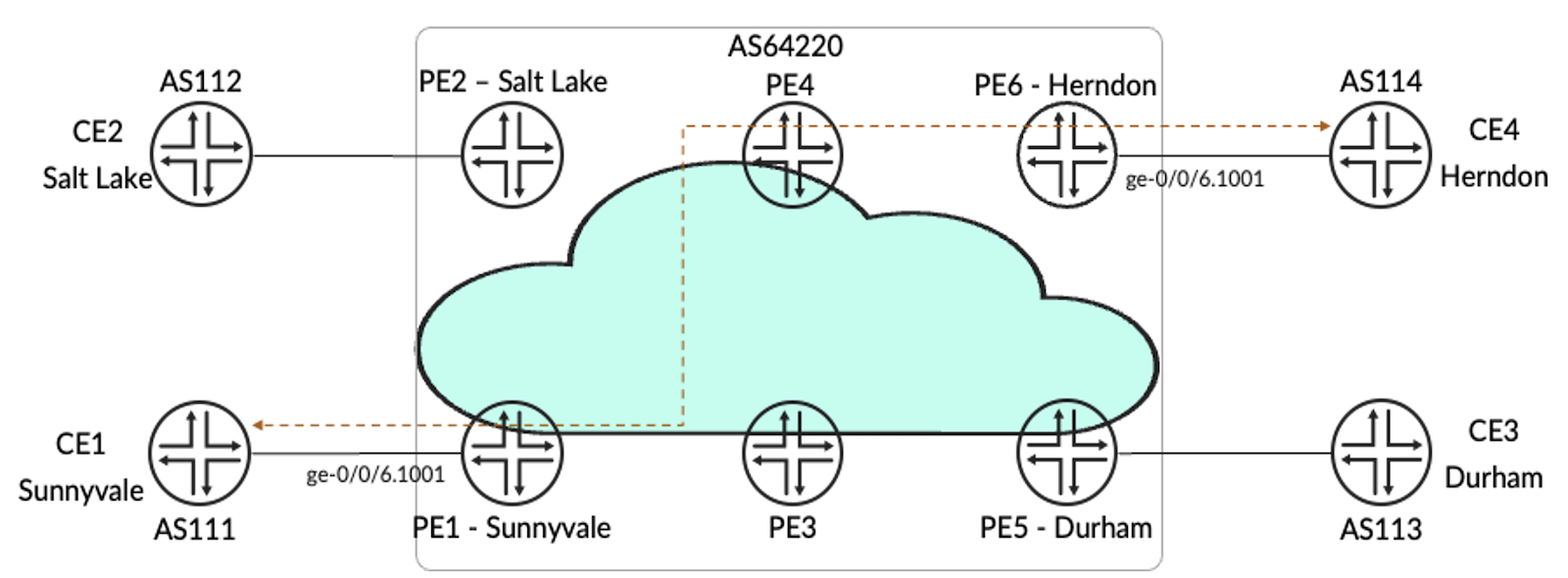
Lastly, we will demonstrate L2Circuit service orchestration. PA supports L2Circuit provisioning and map the service into LSP tunnel. Below is the business intent of the L2Circuit service.
Service will be terminated on Sunnyvale and Herndon
CE-facing interface from PE is ge-0/0/6
VLAN ID: 1001
VC-ID: 100
Bandwidth requirement: 1Gbps
Figure 19: L2Circuit Topology
3.1. Create Service Order
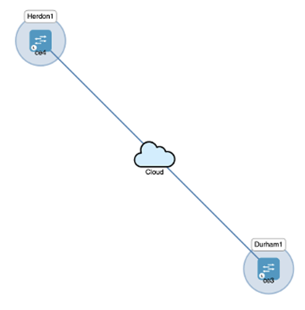
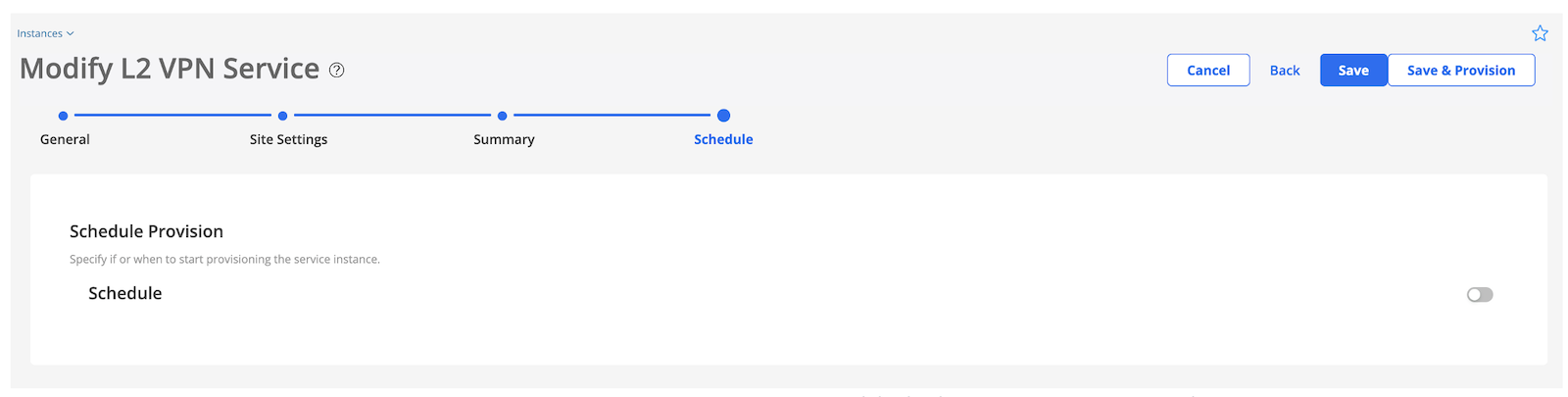
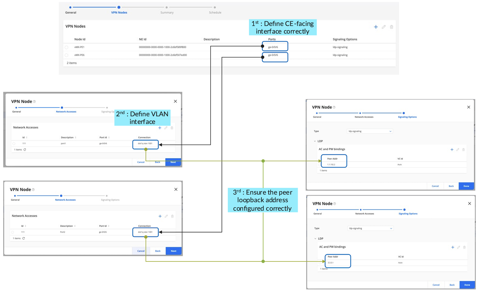
Figure 20 shows the L2Circuit service order created on PA GUI. The L2Circuit consists of 2 sites with ge-0/0/6.1001 as CE-facing interface. Service topology can be previewed and confirmed before order publishment.
Figure 20: Step-by-step L2Circuit Service Provisioning from PA GUI
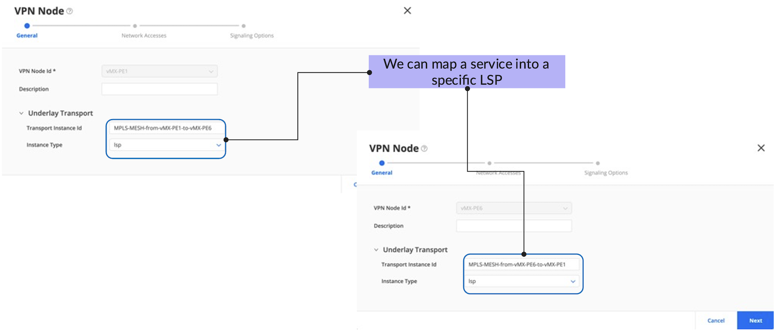
During L2Circuit service orchestration, we can also map an L2Circuit into a specific LSP via community.
Figure 21: L2Circuit Service Map into LSP
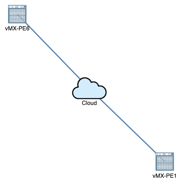
Figure 22: Service Topology in PA GUI
3.2. Publish Service Order
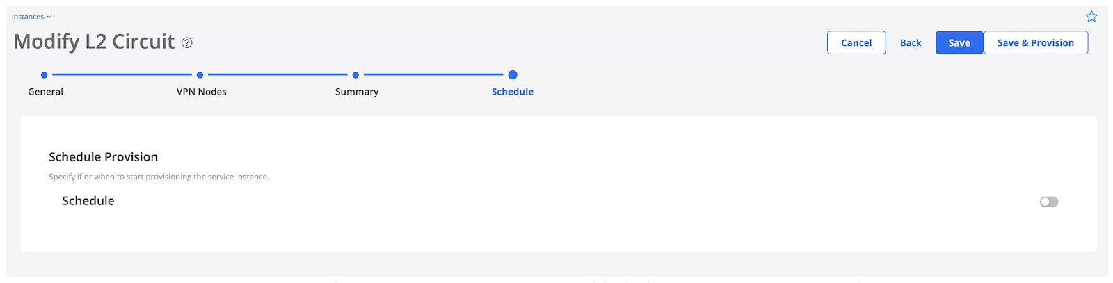
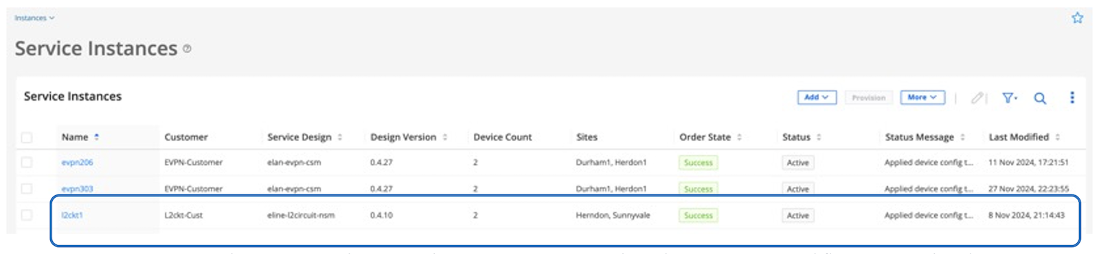
Then, we hit "Save & Provision" to publish the service order. A similar workflow as shown in Figure 16 will be triggered.
Figure 23: Hit "Save & Provision" to publish the L2Circuit service order
Figure 24: The service order status becomes "success" when the L2Circuit workflow is completed.
3.3. L2Circuit Service Provisioning Verification in Routers
jcluser@vMX-PE1> show configuration groups paragon-service-orchestration policy-options
policy-statement 4b686155-9dd3-11ef-b5c3-deba06bc9197-l2ckt1 {
    from community 4b686155-9dd3-11ef-b5c3-deba06bc9197-l2ckt1;
    then {
        install-nexthop lsp MPLS-MESH-from-vMX-PE1-to-vMX-PE6;
    }
}
community 4b686155-9dd3-11ef-b5c3-deba06bc9197-l2ckt1 members 999:0;

jcluser@vMX-PE1> show route 1.1.192.2 table inet.3 -> PE6 loopback address

inet.3: 5 destinations, 10 routes (5 active, 0 holddown, 0 hidden)
+ = Active Route, - = Last Active, * = Both

1.1.192.2/32       *[RSVP/7/1] 00:11:00, metric 2
                    >  to 26.26.26.2 via ge-0/0/1.0, label-switched-path MPLS-MESH-from-vMX-PE1-to-vMX-PE6
                       to 18.18.18.2 via ge-0/0/2.0, label-switched-path Bypass->26.26.26.2
                    [LDP/9] 00:11:21, metric 1
                    >  to 33.33.33.2 via ge-0/0/0.0, Push 301152
                       to 26.26.26.2 via ge-0/0/1.0, Push 301360

jcluser@vMX-PE6> show configuration groups paragon-service-orchestration policy-options
policy-statement 4b686155-9dd3-11ef-b5c3-deba06bc9197-l2ckt1 {
    from community 4b686155-9dd3-11ef-b5c3-deba06bc9197-l2ckt1;
    then {
        install-nexthop lsp MPLS-MESH-from-vMX-PE6-to-vMX-PE1;
    }
}
community 4b686155-9dd3-11ef-b5c3-deba06bc9197-l2ckt1 members 999:0;

jcluser@vMX-PE6> show route 3.3.3.1 table inet.3 -> PE1 loopback address

inet.3: 5 destinations, 10 routes (5 active, 0 holddown, 0 hidden)
+ = Active Route, - = Last Active, * = Both

3.3.3.1/32         *[RSVP/7/1] 00:26:28, metric 2
                    >  to 22.22.22.2 via ge-0/0/2.0, label-switched-path MPLS-MESH-from-vMX-PE6-to-vMX-PE1
                       to 25.25.25.2 via ge-0/0/0.0, label-switched-path Bypass->22.22.22.2
                    [LDP/9] 00:26:35, metric 1
                    >  to 22.22.22.2 via ge-0/0/2.0, Push 300800
                       to 16.16.16.1 via ge-0/0/3.0, Push 300800
jcluser@vMX-PE1> show l2circuit connections
Layer-2 Circuit Connections:

Legend for connection status (St)
EI -- encapsulation invalid      NP -- interface h/w not present
MM -- mtu mismatch               Dn -- down
EM -- encapsulation mismatch     VC-Dn -- Virtual circuit Down
CM -- control-word mismatch      Up -- operational
VM -- vlan id mismatch           CF -- Call admission control failure
OL -- no outgoing label          IB -- TDM incompatible bitrate
NC -- intf encaps not CCC/TCC    TM -- TDM misconfiguration
BK -- Backup Connection          ST -- Standby Connection
CB -- rcvd cell-bundle size bad  SP -- Static Pseudowire
LD -- local site signaled down   RS -- remote site standby
RD -- remote site signaled down  HS -- Hot-standby Connection
XX -- unknown

Legend for interface status
Up -- operational
Dn -- down
Neighbor: 1.1.192.2
    Interface                 Type  St     Time last up          # Up trans
    ge-0/0/6.1001(vc 100)     rmt   UP     Nov 8 21:14:43 2024           1

jcluser@vMX-PE6> show l2circuit connections
Layer-2 Circuit Connections:

Legend for connection status (St)
EI -- encapsulation invalid      NP -- interface h/w not present
MM -- mtu mismatch               Dn -- down
EM -- encapsulation mismatch     VC-Dn -- Virtual circuit Down
CM -- control-word mismatch      Up -- operational
VM -- vlan id mismatch           CF -- Call admission control failure
OL -- no outgoing label          IB -- TDM incompatible bitrate
NC -- intf encaps not CCC/TCC    TM -- TDM misconfiguration
BK -- Backup Connection          ST -- Standby Connection
CB -- rcvd cell-bundle size bad  SP -- Static Pseudowire
LD -- local site signaled down   RS -- remote site standby
RD -- remote site signaled down  HS -- Hot-standby Connection
XX -- unknown

Legend for interface status
Up -- operational
Dn -- down
Neighbor: 3.3.3.1
    Interface                 Type  St     Time last up          # Up trans
    ge-0/0/6.1001(vc 100)     rmt   UP     Nov 8 21:14:43 2024           1
In this TechPost, we have introduced intent-based service orchestration on Paragon Automation. L3VPN, EVPN, and L2Circuit service provisioning are demonstrated and orchestrated with complex workflows such as service design, assurance of VPN resources in the network, device configuration, and orchestration with active assurance for SLA measurement. The whole process is fully automated and only takes minutes to complete. Thanks to Paragon Automation, intent-based service orchestration reduces complexity and OpEX, accelerates time to revenue, and enhances service quality.