SP-style Config in Apstra Freeform for VLAN Overlap Use-Cases
Elisabeth Rodrigues - 03/25/2024
In high multi-tenant environments such as Service Providers, Hosting Providers, or just large enterprises, having to deal with multiple internal customers, efficient utilization of infrastructure is top of mind for network operations teams. While ensuring isolation and security among different users or departments, you also want to leverage network virtualization techniques to support full overlap of resources between those users. This not only speeds up the onboarding process for new customers, and companies you acquire, but it also preserves your infrastructure investment allowing you to deliver more with the same network infrastructure.
Introduction
This blog post describes the steps of implementing multi-tenancy in an EVPN-VxLAN data center fabric. We will delve into the intricacies of control-plane and data-plane details and how they are combined to fulfill layer 2 and layer 3 overlap. We will then use Apstra Freeform to design and deploy such a network.
The term "Multi-tenancy" applying to a broad range of domains, this blog post focuses on the resources overlap. What is outside of the scope of this post is the Multi-tenancy concept related to the user management part and any permission enforcement, in other words, the management plane. For that, watch out for an upcoming blog post for new capabilities coming soon on Juniper Apstra.
Refresher on EVPN VxLAN
EVPN supports multiple service interface types. Depending on the service interface defined, either all traffic on an interface, or traffic on a specific VLAN, or traffic on a list/range of VLANs can be mapped to a Bridge Domain (BD). That Bridge Domain is then associated with an EVPN instance (EVI) for forwarding VxLAN-encapsulated traffic across the IP fabric. An EVPN instance represents an L2 VPN instance on a switch, also known as a MAC-VRF in Junos implementation.
How does the segregation happen at the Control-plane vs. Data-plane level?
- Control-plane separation: depending on the EVPN service interface defined, EVIs are assigned import/export Route Targets (RTs) and Route Distinguisher (RD).
- Data-plane separation: VNI field of the VxLAN header is used during packet lookup to place onto the right Bridge-Domain/VLAN.
The L3 EVPN instance serves the same role as an IP VPN (VRF), but in this case is an EVPN VRF, sometimes referred to as Type-5 VRF due to the EVPN Type-5 routes. This ensures L3 overlap. What we would like to do is to push this further by also leveraging EVPN for L2 overlap.
A MAC-VRF or EVI can offer 3 types of service interface types:
- VLAN-based: Single VLAN broadcast domain and single bridge domain. Every VLAN-id is mapped to one Bridge Domain, mapped to one VNI, and one has its own route-target.
- VLAN-aware: Multiple VLAN broadcast domains with each VLAN having its own bridge domain. Every VLAN is mapped to one VNI and can have its own route-target. This is the preferred option for most enterprises.
- VLAN-bundle: Multiple VLAN broadcast domains sharing a single bridge domain, MAC addresses must be unique. All VLAN-ids are mapped to the same VNI and the same route-target. The VLAN-id is encapsulated in the VXLAN packet. This option helps to overlap the VLAN-ids but also to deliver a higher VLAN scale. This is a typical option for hosting companies.
What does Apstra Datacenter Reference Design Support?
On Juniper fabrics, Apstra Datacenter reference design configures EVPN VXLAN with multiple EVPN VRFs and a single MAC-VRF of service interface type VLAN-aware. The Junos configuration style used is "Enterprise Style".
Enterprise Style vs SP Style with Junos ?
Enterprise style is simpler and needs less configuration.
Here is an example of an interface with multiple VLANs using enterprise-style :
SP Style Offers greater flexibility but requires more configuration steps.
Here is the same example using SP-Style :
On top of that, each logical interface must be added to the appropriate bridge-domain.
Challenges of a Multi-Tenant Datacenter and How We Solve Them?
When you run a highly multi-tenant environment such as a shared EVPN-VxLAN fabric hosting several customers with the goal to offer each of them as much flexibility as possible, you often have to deal with L2 and L3 overlap. Let's dissect each one of them.
L3 Overlap
This happens when the tenants use the same IP space.
Solution: this can be easily solved using EVPN T5 VRFs. Each tenant will have one or multiple VRFs ensuring IP subnet uniqueness and avoiding any duplicate.
L2 Overlap
This happens when the tenants use the same VLAN-id space.
We can distinguish 2 use cases:
- There is no need for VLAN-id overlap at the leaf level. This can be easily addressed with the Apstra Datacenter reference design. In that case, each virtual network is assigned a different VNI and the VLAN-id association is configured for each leaf.
- There is a need for VLAN-id overlap at the leaf level. There are several ways to address it:
We can use Configlets in the Datacenter Reference design to push additional configurations based on the Junos functionality called "VLAN Rewrite". This additional configuration allows you to define translation rules where a given VLAN ID is rewritten to use another VLAN ID. It is a simple configlet, and represents a good solution for a temporary use, typically during a migration time. We can use SP-Style configuration. - Level 3 multi-tenancy : each tenant is separated by a L3 domain.
Example Description
This example utilizes Apstra release 4.2.1
Apstra is the Single Source of Truth.
In this example, ESXi-110 and ESXi-114 use the same vlan-id but belong to different tenants and must be encapsulated in different VNIs.
Here is the lab topology:
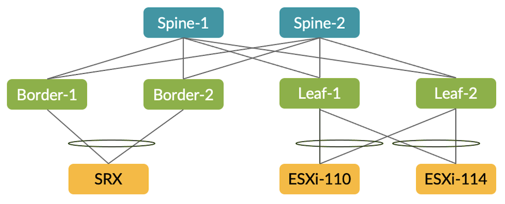
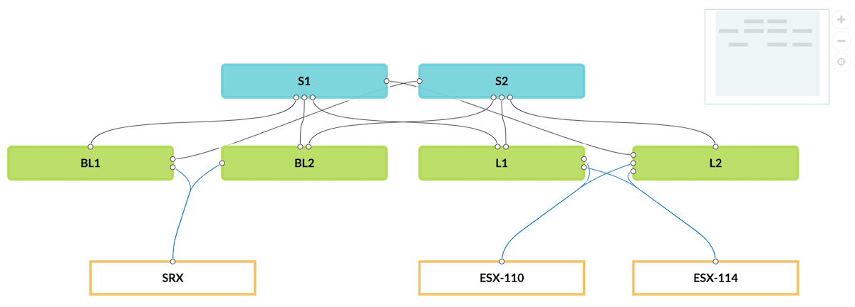
Network Design With the Topology Editor
Create a new Freeform blueprint and design the topology with the topology editor:
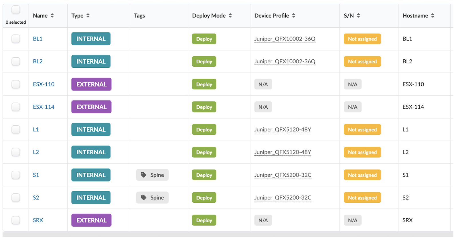
Identify the spines with a tag:
Resource Management
Create the following resources in the resource menu and allocate them in the blueprint.
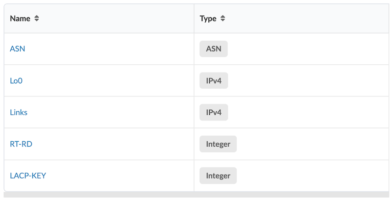
In the Resource Management Menu, Blueprint Resources, create a group named Cloud.
ASN Allocation
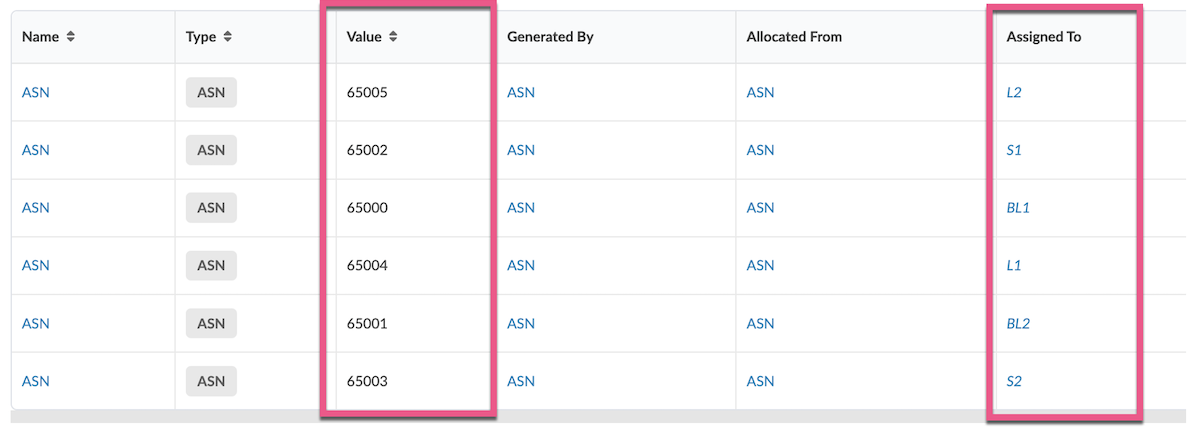
Allocate an ASN to each managed device, all spines, all leaves, and border leaves.
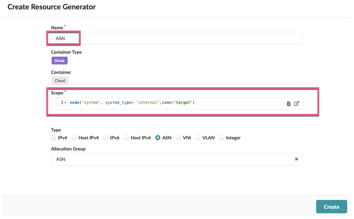
The result is the following.
Loopback Allocation
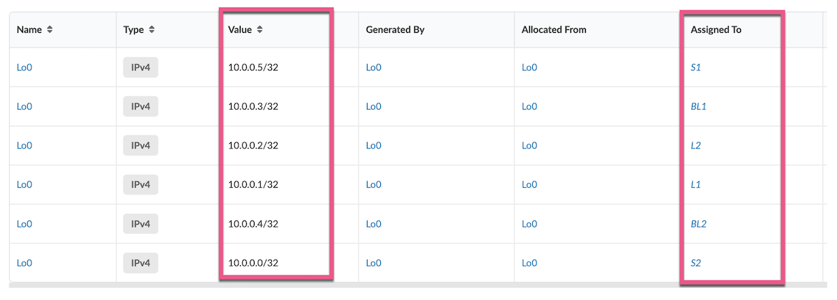
Allocate a loopback IP to each managed device, all spines, all leaves, and border leaves.
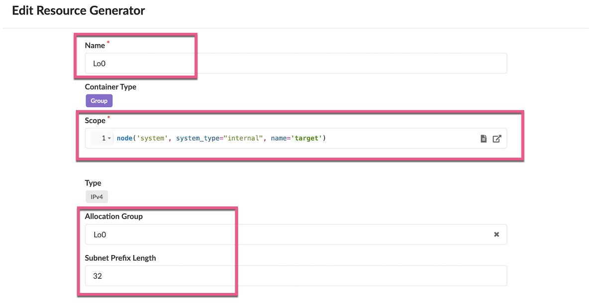
The result is the following.
IP Links Allocation
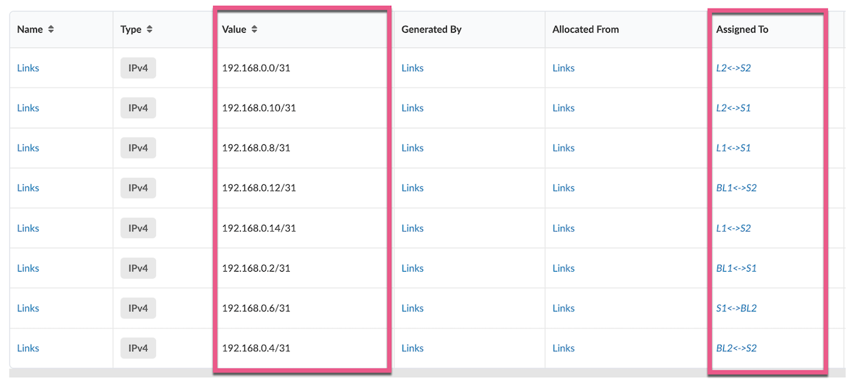
Allocate a /31 subnet to each internal link between all spines and all leaves / border leaves.
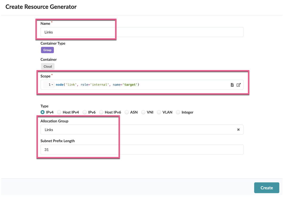
The result is the following.
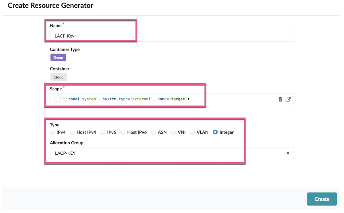
LACP Key Allocation
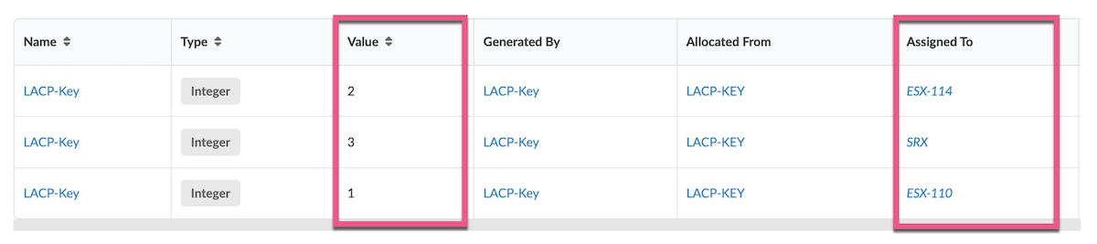
Allocate an integer to each external device. This value will be used to generate a unique LACP key to each connected device.
The result is the following:
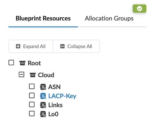
All the resources created appear in the Blueprint resources:
Config Templates
After allocating the resources, we need to apply the Junos command lines to configure the devices.
Create the following configuration templates.
ASN Configuration template
Create the following Configuration Template "Cloud_ASN.jinja"
Rendered configuration on L1
Loopback Configuration template
Create the following Config Template "Cloud-Loopback.jinja"
Rendered configuration on L1
eBGP Underlay Configuration Template
Create the following Config Template "Cloud_eBGP-Underlay.jinja"
Rendered configuration on L1
eBGP Overlay Configuration Template
Create the following Config Template "Cloud_eBGP-Overlay.jinja"
Rendered configuration on L1
ESI-LAG Configuration Template
Create the following Config Template "Cloud_LAG.jinja"
Rendered configuration on L1:
Tenants design and configuration
Each tenant is a unique MAC-VRF.
Each MAC-VRF will have the following attributes:
- A VRF Target
- A Route-Distinguisher for each leaf/border leaf
- A list for VLANs
- Optionally, an IRB for each defined VLAN
Here is how we define a Tenant in the Resource Management > Blueprint Resources:
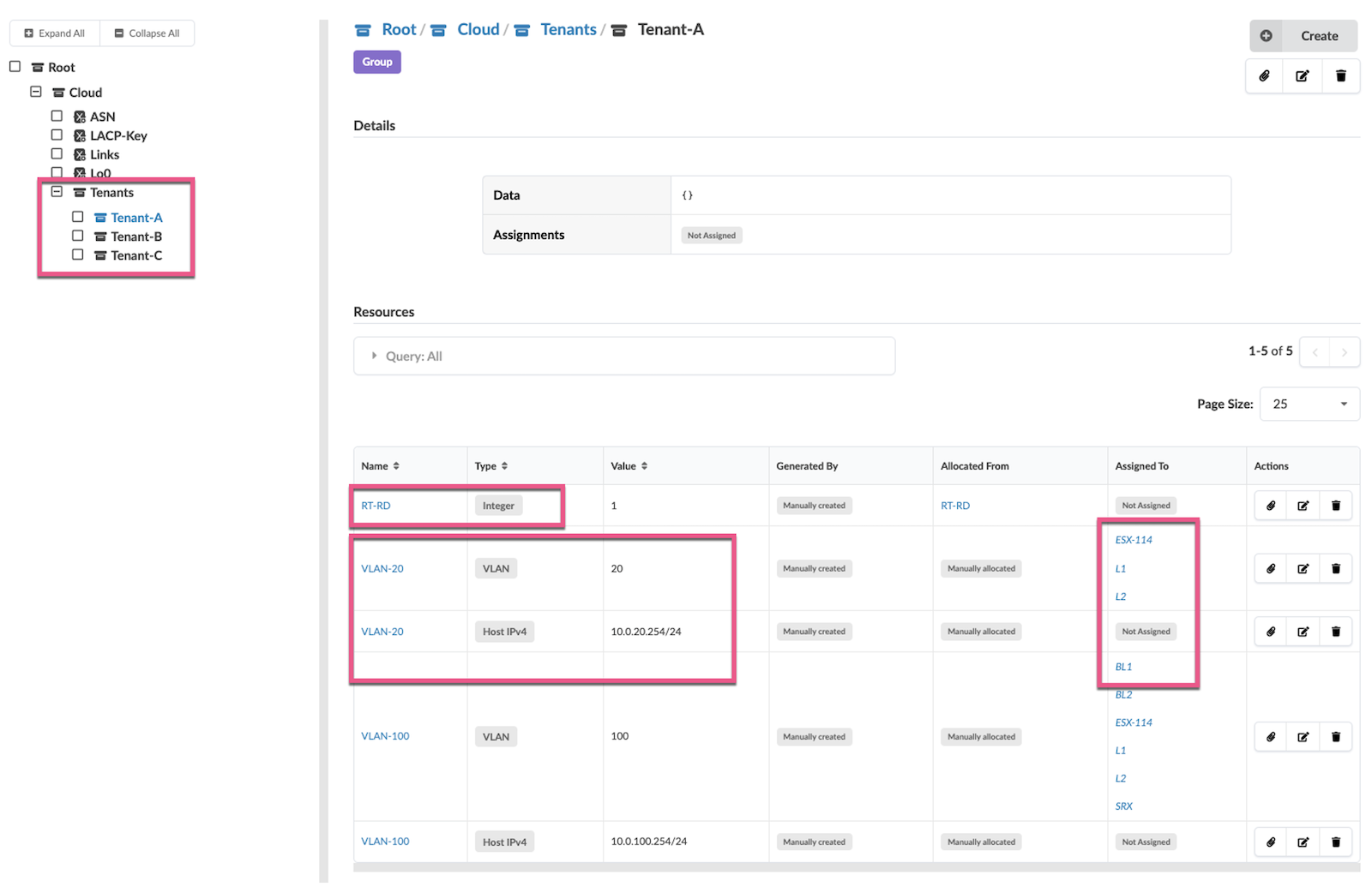
The physical interfaces are assigned to a tenant and a list VLANs by using the assignment button on the right. Here we can see that ESX-114 is assigned to VLAN-20 and Tenant-A.
Tenant Configuration template
1 2 3 4 5 6 7 8 9 10 11 12 13 14 15 16 17 18 19 20 21 22 23 24 25 26 27 28 29 30 31 32 33 34 35 36 37 38 39 40 41 42 43 44 45 46 47 48 49 50 51 52 53 54 55 56 57 58 59 60 61 62 63 64 65 66 67 68 69 70 71 72 73 74 75 76 77 78 79 80 81 82 83 84 85 86 87 88 89 90 91 92 93 94 95 96 97 98 99 100 101 102 103 104 105 106 107 108 109 110 111 112 113 114 115 116 117 118 119 120 121 122 123 124 125 126 127 128 129 130 131 132 133 134 | |
Rendered Config on L1 for Tenant A:
Global Configuration Template
Change the junos configuration template "junos_configuration.jinja" as follow :
Conclusion
Apstra Freeform allows you to design and manage multi-tenant data center networks with an unprecedented level of design flexibility. The unique Apstra Freeform capability of resource generators is a powerful capability that you can use to streamline the allocation of network resources. This functionality facilitates the creation of highly customized and efficient network configurations by dynamically generating necessary parameters such as Autonomous System Numbers (ASNs), loopback addresses, and VLAN IDs across the entire fabric. By doing so, Apstra Freeform significantly reduces the manual overhead typically associated with configuring and managing complex, multi-tenant networks
Glossary
- ASN: Autonomous System Number
- BGP: Border Gateway Protocol
- EVPN: Ethernet Virtual Private Network
- ESI: Ethernet Segment Identifier
- EVI: EVPN Instance
- NOS: Network Operating System
- RBAC: Role Based Access Control
- RD: Route Distinguisher
- RT: Route Targer
- VXLAN:
- ZTP: Zero Touch Provisionning
Acknowledgements
I would like to thank Mehdi Abdelouahab for reviewing and adding valuable and insightful content to this article.