Let's Talk About VOQ and DNX Pipeline
To understand the life of a packet in an ACX7000 Series router, you first need to understand the idea behind Virtual Output Queues.
Introduction
Many Network Processing Unit (NPU) architectures are available on the market today. They propose different packet buffering approaches, performed in both ingress and egress datapaths (sometimes referred to as "2-stage buffering architecture") or in the ingress pipeline only. That second case includes the DNX chipsets powering Juniper ACX Series. More details on the DNX options and their architecture has been covered in the first article of the series: https://juniper.github.io/techposts/building-the-acx7000-series-the-pfe/article
In this article, we describe this packet buffering logic by following the life of a packet, and we introduce the concept of a Virtual Output Queue (VOQ).
The concept described here will be useful for all follow up articles on ACX7k platforms since these principles are common to all products in this family.
Ingress-only Buffering
DNX ASICs used in ACX7000 Series are based on a pipeline design where the packet memory is present in the ingress part.
We talk about "ingress-only buffering model" but in all fairness, we should probably call it "ingress-mostly buffering". Indeed, a small packet buffer is still present in the egress pipeline, but it's a very shallow space compared to the very large High-Bandwidth Memory (HBM) used off-chip and reachable from the ingress pipeline.
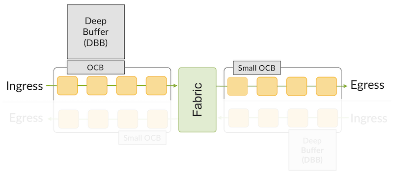
In normal traffic conditions, the packets are stored in the ingress On-Chip Buffer (OCB). It's only when a queue is getting congested that packets are moved to the Delay Bandwidth Buffer (DBB) or "Off-Chip Buffer". This second memory type will be an HBM or DDR.
This mechanism of queue eviction to an off-chip buffer and return to an on-chip buffer occurs dynamically as soon as a threshold is exceeded.
The small on-chip buffer on the egress pipeline can be used to store packets before they are sent to the interface and can only discriminate between high and low priority. It doesn't have the size nor the structure to perform Quality of Service (QoS) treatment.
To compare the different memory sizes, let's take the Jericho2 NPU example:
- The ingress on-chip buffer is 32 MB (16 per core)
- The ingress off-chip buffer is 8 GB (shared)
- The egress on-chip buffer is 12 MB (6 per core)
Using an ingress-only deep buffer offers multiple advantages:
- It reduces by half the memory requirement
- It reduces the footprint on the Printed Circuit Board (PCB)
- It reduces the latency
- It reduces power consumption
- Eventually, it optimizes the cost
Everything in technology is a trade-off, it creates other challenges. When the packets are stored in egress before transmission, it's easy to classify them and apply different treatments with QoS policies. But when packets are buffered in potentially dozens of ingress PFEs (Packet Forwarding Engines), we need a new mechanism to guarantee the forwarding efficiency. It requires fast communication between the ingress pipeline and its egress counterpart. We are talking about "scheduling".
Scheduled Forwarding and Virtual Output Queues
How does it work then?
When a packet is received in a port, it starts its journey in the ingress pipeline. A lookup determines the packet destination, and a classification associates the traffic to a queue. But again, the queues are not present in the outbound path, so we need to create a virtual representation of this pair (destination port, queue) that can be associated with every packet stored in the ingress pipeline.
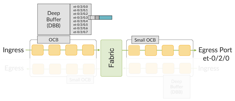
In Diagram 2 above, we represent the queues created, from the ingress pipeline perspective, for port et-0/2/0. Note that it's not necessarily limited to a physical port, we can create "attach points" for these queues and it could be an IFL (logical interface, like a sub-interface for example).
When packets are received:
- Destination lookup is done, itself "resolved" to a destination interface (or again, an attachment point)
- Classification will be performed to differentiate packet class, by default or dictated by a QoS policy, eventually associating the packet to a queue.
At the end of the operation, we can store the packet in the buffer (for the sake of simplicity, let's imagine it will be done in the off-chip buffer, but the same logic applies to on-chip). The system stores the packet with an internal header representing the pair (destination port, queue) represented by a number. This number is a Virtual Output Queue Identifier (VOQ ID). Again, I insist on this important aspect, the queues are not carved in memory. It should be seen as a flag added to the packet.
To put it differently, a VOQ is the virtual representation of a queue and an egress port, but from the ingress pipeline perspective, where the buffering is actually done.
This representation exists for the port itself, as presented in the example below in the ingress NPU on 0/1 manages the queues of local ports like et-0/1/0 and remote ports like et-0/2/0. Same thing for the ingress structure of the NPU(s) on 0/2 handling the queues for remote port et-0/1/0 and local port et-0/2/0.
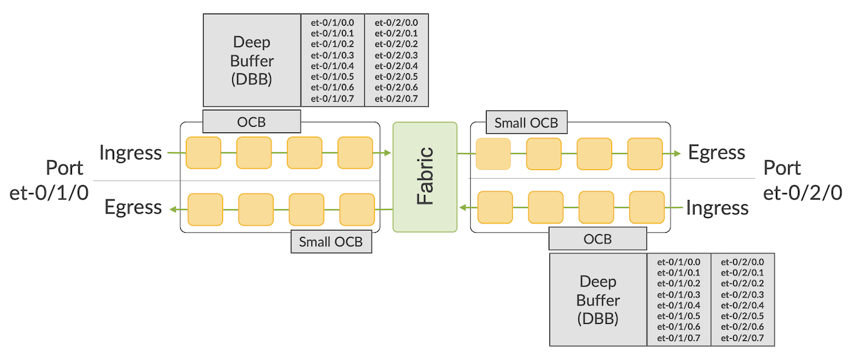
The treatment is the same if the packet is targeted to the same interface it comes from (loopback or routing to a different VLAN) or if it will be sent to a remote port.
We can go further with the idea, if we have 1,000 egress ports or attachment points, we will need to create 1,000 sets of 8 queues (total 8,000 queues) on all PFEs present in the router. If it's a modular chassis made of 24 PFEs, I will need to create this 8,000-queue structure in all 24 ASICs.
That's why, by default, a VOQ scale should be considered a global number. If your ASIC supports 64,000 VOQs, it means the entire router supports 64,000 queues and all egress ports will need to share this pool. It's a fundamental difference compared to systems where packets are stored in ingress and egress paths, like the Trio chipset in the MX Series.
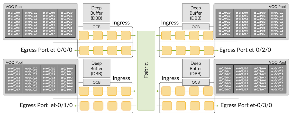
To illustrate it, Diagram 4 above represents 4 different egress interfaces located on 4 distinct PFEs. You can extend the idea to thousands of ports (it's just pretty hard to illustrate on a diagram ;))
Life of a Packet
In the ingress pipeline, we will break the process into four steps:
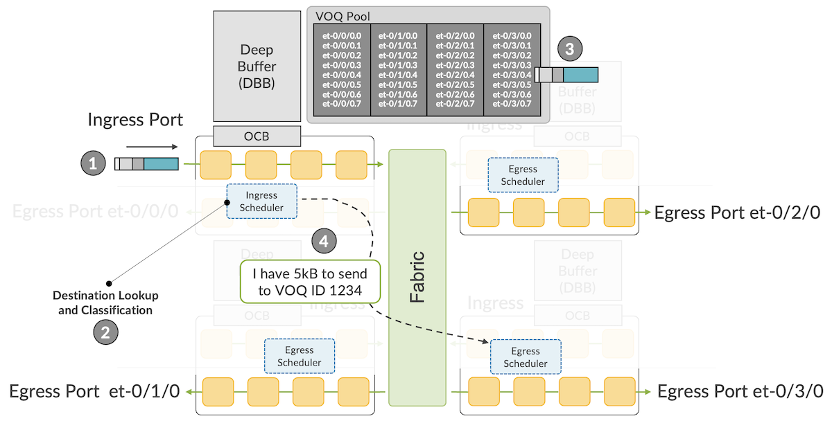
- A packet is received on port et-0/0/0 (mapped to the core 0 of the PFE 0/0)
- In this ingress pipeline, multiple blocks will treat the packet, determining where the packet is meant to be sent to, and which class of traffic it belongs to. This will help figure out an egress port (and the egress PFE associated) and a queue, represented by a VOQ ID. In our example, port et-0/3/0 and queue 5, VOQ 1234
- The packet is stored in HBM, with additional internal headers, including information like the VOQ ID. The system keeps track of the memory position used to store this packet.
- The Ingress Scheduler informs the destination Egress Scheduler present in the PFE pipeline associated with the port et-0/3/0 that it has 5kB of traffic for this particular VOQ. And that's all it will do now until further notification.
For the egress part of the process, let's imagine our Egress Scheduler on PFE 0/3 received solicitations to transmit packets to interface et-0/3/0 from 3 different ingress PFEs.
From PFE 0/2 (top right of the diagram), it received a solicitation for a high-priority packet in port et-0/3/0 queue 7 (VOQ ID 3445).
And from PFE 0/0 and 0/1 it received a solicitation for packets targeted to port et-0/3/0 queue 4, the best effort queue (VOQ ID 1234).
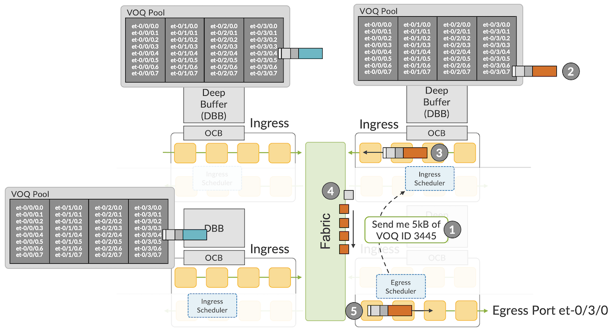
Our egress PFE has 3 solicitations to address and based on the QoS configuration, it will decide that the high-priority packet from PFE 0/2 needs to be transmitted.
- The Egress Scheduler will generate a token or grant, to the Ingress Scheduler of PFE 0/2 (top right), for a specific amount of traffic.
- With this "right to transmit" the Ingress Scheduler will trigger the dequeue of this high-priority packet
- It will continue its journey in the last blocks of the ingress pipeline. The last step will consist in splitting the packets into cells and spraying them among the available fabric interfaces
- The cells are routed to the destination PFE in the fabric
- Cells are re-assembled and the high-priority packet continues its journey in the egress pipeline, with a short buffering in the "EGQ" (Egress port Queue). In that step, a very basic classification will occur, differentiating high from low priority packets and unicast from multicast. After all egress features are applied, the packet is transmitted to its next-hop via et-0/3/0
The system is now ready to service the two remaining solicitations. Since they have the same destination and queue, they have the same priority and will be treated in a round-robin fashion. The same 5 steps described above will be executed, a token sent to the Ingress Scheduler, the packets "cell-ified" will travel to the destination PFE via the fabric interfaces, and they will be eventually transmitted to port et-0/3/0.
In this model, the packet forwarding is "scheduled", which means it relies entirely on the constant and extremely fast communication between all ingress and egress schedulers of the different PFEs in the system.
Note: the total traffic to port et-0/3/0 queue 4 is not really measured on the egress PFE, but it's the sum of all the requests to transmit scattered among all ingress PFEs. That makes the traffic accounting a bit more challenging in very large multi-PFE systems.
It also applies to system-on-the-chip (SoC) architectures, even if they are made of a single core (like the Jericho2c for example).
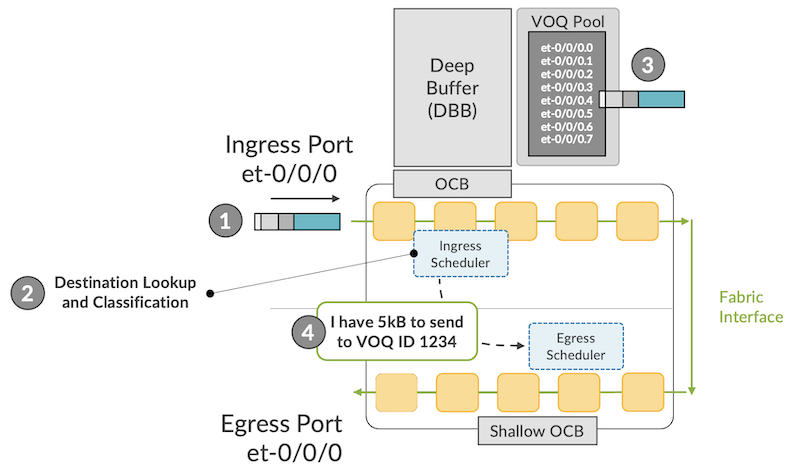
In the ingress direction, we have the same steps as described earlier, with the only difference, the destination resolution points to a local interface. But whether the egress pipeline is local or remote, it makes no difference from the ingress scheduler's perspective, it simply informs the destination of its desire to transmit traffic to a specific VOQ.
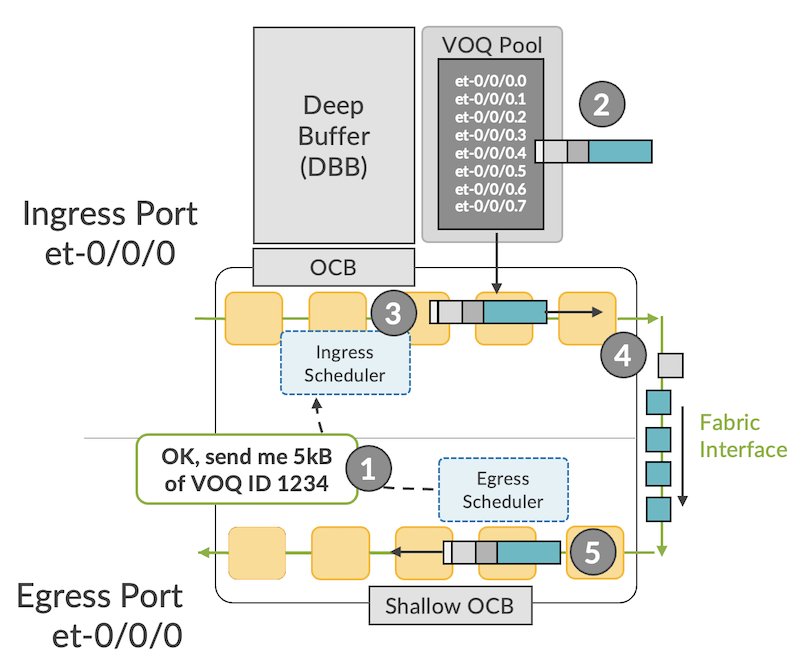
On the egress side too, no difference if the request went from a distant or a local scheduler. It will decide the allocation of tokens/rights to transmit based on the quality of service configuration. Even if everything happens in the same PFE core, the packets are still "cell-ified" to be transmitted to the fabric interface, and the cells are re-assembled when arriving in the egress pipeline.
Illustration with CLI
You'll understand now the key concept: the queues for a specific egress port are scattered all around the router. Refer to this article to understand the different Packet Forwarding Engines (PFE) used in the different ACX7k family members: https://juniper.github.io/techposts/building-the-acx7000-series-the-pfe/article
If it's a single PFE device (aka SoC/RoC for System/Router on a Chip), the queues are naturally present on this single NPU, as it's the case for an ACX7100-32C or ACX7100-48L:
In the example of ACX7100-32C above, we consider the first four 100GE ports.
The VOQ Base ID represents the first VOQ ID for an interface. The system allocates 8 VOQ IDs per interface, but you'll notice with have 16 between et-0/0/0 and et-0/0/1 and 32 between et-0/0/0 and et-0/0/2...
It's simply because port et-0/0/0 can be used with a breakout cable and four ports. It will disable the port et-0/0/1 so we will have 4 channelized interfaces from et-0/0/0:0 to et-0/0/0:3, each one will be allocated 8 VOQs.
In the next example, we are considering an ACX7509. It's a centralized platform based on two REs and two FEBs. Each forwarding board contains two Qumran2C in a back-to-back configuration.
Logically, half of the ports will be connected on one PFE and the other half to the second PFE.
1 2 3 4 5 6 7 8 9 10 11 12 13 14 15 16 17 18 19 20 21 22 23 24 25 26 27 28 29 30 31 32 33 34 35 36 37 38 39 40 41 42 43 44 45 46 47 48 49 50 51 52 53 54 55 56 57 58 59 60 61 62 63 64 65 66 67 68 69 70 71 72 73 74 75 76 77 78 79 80 81 82 83 84 85 86 87 88 89 90 91 92 93 94 95 96 97 98 99 100 101 102 103 104 105 106 107 108 109 110 111 112 113 114 115 116 117 118 119 120 121 122 123 124 125 126 127 128 129 130 131 132 133 134 135 136 137 138 139 140 141 142 143 144 145 146 147 148 149 150 151 152 153 154 155 156 157 158 159 160 161 162 163 164 165 166 167 168 169 170 171 172 173 174 175 176 177 178 179 180 181 182 183 184 185 186 187 188 189 190 191 192 193 194 195 196 197 198 199 200 201 202 203 204 205 206 207 208 209 210 211 212 213 214 215 216 217 218 219 220 221 222 223 224 225 226 227 228 229 230 231 232 233 234 235 236 237 238 239 240 241 242 243 244 245 246 247 248 249 250 251 252 253 254 255 256 257 258 259 260 261 262 263 264 265 266 267 268 269 270 271 272 273 274 275 276 277 278 279 280 281 282 283 284 285 286 287 288 289 290 291 292 293 294 295 296 297 298 299 300 301 302 303 304 305 306 307 308 309 310 311 312 313 314 315 316 317 318 319 320 321 322 323 324 325 326 327 328 329 330 331 332 333 334 335 336 337 338 339 340 341 342 343 344 345 346 347 348 349 350 351 352 353 354 355 356 357 358 359 360 361 362 363 364 365 366 367 368 369 370 371 372 373 374 375 376 377 378 379 380 381 382 383 384 385 386 387 388 389 390 391 392 393 394 395 396 397 398 399 400 401 402 403 404 405 406 407 | |
You notice in these CLI outputs that we can display the aggregated stats in the show interface queue while we display the stats of the VOQ for each individual PFE with the show interface voq command.
In this ACX7509 case above, we just have two PFEs.
But the output will become much longer with a chassis form factor like the ACX7908. In this last example below, we have 3 line cards (FPC):
- Slot 2: FPC with a single PFE
- Slot 3: same kind of FPC with a single PFE
- Slot 6: denser FPC with 3 PFEs
1 2 3 4 5 6 7 8 9 10 11 12 13 14 15 16 17 18 19 20 21 22 23 24 25 26 27 28 29 30 31 32 33 34 35 36 37 38 39 40 41 42 43 44 45 46 47 48 49 50 51 52 53 54 55 56 57 58 59 60 61 62 63 64 65 66 67 68 69 70 71 72 73 74 75 76 77 78 79 80 81 82 83 84 85 86 87 88 89 90 91 92 93 94 95 96 97 98 99 100 101 102 103 104 105 106 107 108 109 110 111 112 113 114 115 116 117 118 119 120 121 122 123 124 125 126 127 128 129 130 131 132 133 134 135 136 137 138 139 140 141 142 143 144 145 146 147 148 149 150 151 152 153 154 | |
The pipeline
You can find a lot of details in the Traffic Management Architecture Design Guide here: https://docs.broadcom.com/doc/88800-DG1-PUB
To summarize the key concepts, we can represent the pipeline like this:
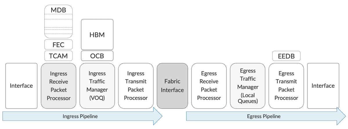
Packets are received from ingress interfaces, but this description doesn't only apply to network interfaces (NIFs). Traffic could also come from the:
- Recycle interfaces
- CPU interface
- OAMP (Operation and Maintenance Processor) interface
- SAT (Service Availability Testing) interface
- And some others like OLP (Offload Processor) interfaces
The first 144 bytes of each packet are sent to the IRPP (Ingress Receive Packet Processor).
- IRPP takes care of the majority of the features, including the identification of the incoming interface, the lookup (L2, L3, MPLS, ...), the next hop resolution and load balancing, the filtering, the insertion of internal headers and many more
- ITM handles the queues, on-chip or off-chip. That's also where the multicast replication can be performed
- ITPP is the last step before the fabric interface, packets can be edited here also
- ERPP manages some of the egress features like filtering
- ETM handles the queues from the egress perspective and can also perform multicast replication
- ETPP can edit packets based on indication from the ingress pipeline (present in the internal headers)
Conclusion
This article provided some details on the life of a unicast packet in the DNX-based systems and presented the concept of Virtual Output Queue, essential to understand how the ACX7k Series products operate. In the next articles, we will dig deep into the internals of each ACX7k family members.
Useful links
- https://docs.broadcom.com/doc/88800-DG1-PUB
- Building the ACX7000 Series - The PFE: https://juniper.github.io/techposts/building-the-acx7000-series-the-pfe/article
Glossary
- CoS/QoS: Class of Service / Quality of Service
- DBB: Delay Bandwidth Buffer
- DDR: Double Data Rate (Memory)
- EGQ: Egress Queue
- HBM: High Bandwidth Memory
- IFL: Logical Interface
- PFE: Packet Forwarding Engine
- NPU: Network Processing Unit
- OAMP: Operation and Maintenance Processor
- OCB: On-Chip Buffer
- OLP: Offload Processor
- SAT/ Service Availability Testing
- TM: Traffic Manager
- VOQ / VOQ ID: Virtual Output Queue / Identifier
- SoC: System on a Chip
Acknowledgements
Thanks a lot to Biju Kumar Karunakaran Nair for all the details on queueing and review of this document.